SOM-1655-002.pdf - 第28页
27 Tg0742-PM-SO 8. T roubleshooting after Error Window (Error ID) Assuming "Error ID/Item/Description" in the "ERROR" window as an index, retrieve the related page of the instruction manual. Refer to …
26 Tg0742-PM-SO0301-001
7. Component Library
Fig. 11
Sampling scan mode
All scan :
The V. bend detection is made for all leads.
Mode 1 (Sampling) :
The V. bend detection is made periodically. The first test,
of the number of detection times set in "Sampling scan", is
made.
Sampling scan frequency 1
The frequency for the V. bend detection is set.
When the "Sampling scan mode" is set to "Mode 1 (Sam-
pling)", the first test, of the number of detection times
there, is made.
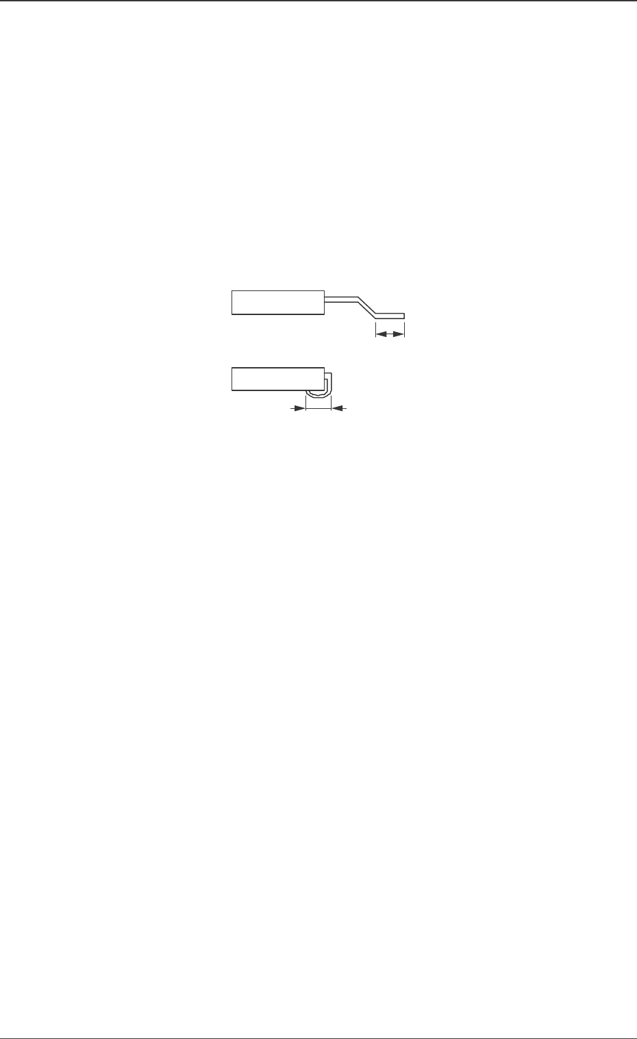
Soldered posn length set
Auto (Default) :
With gull-wing, half the total length of the lead is set.
For J bend, the total length of the lead is set.
Manual :
The "Soldered posn length" is set manually.
Soldered posn length
It is displayed when the "Soldered posn length set" is to be
set manually.
The length of the lead to be soldered is entered.
27 Tg0742-PM-SO
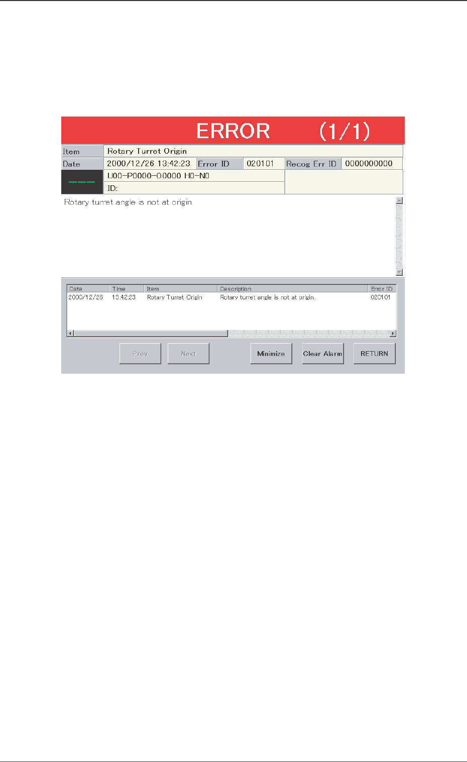
8. Troubleshooting after Error Window (Error ID)
Assuming "Error ID/Item/Description" in the "ERROR" window as an
index, retrieve the related page of the instruction manual.
Refer to "Typical Description" for the detailed description.
Fig. 12 Example of "ERROR" Window
0301-001
8. Troubleshooting after Error Window (Error ID)
28 Tg0742-PM-SO0301-001
8. Troubleshooting after Error Window (Error ID)
Typical Description
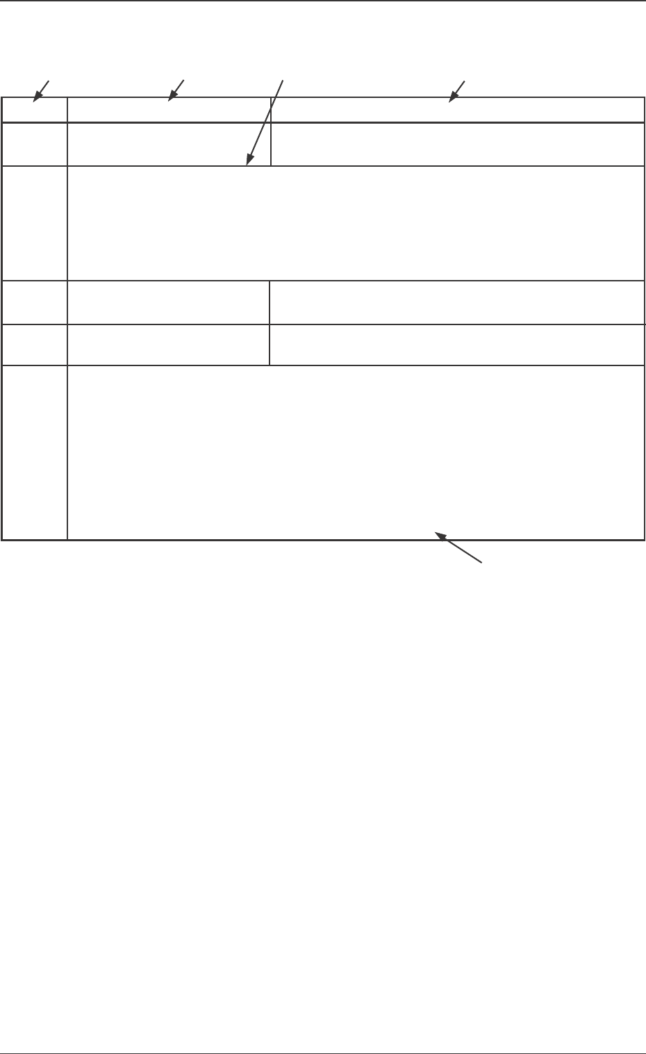
Table 1
Error ID Item Description
050301 Y2 Axis Data The driver data was detected outside of the possible range.
(Cause 1) Self-Diagnostics Error Message
(Remedy 1) Zero all axes and re-start the operation.
When the machine cannot be set to its normal condition, consult our service
personnel for the remedy.
050401 Y2 Axis Limit (+) Limit error has been detected.
050402 Y2 Axis Limit (-) Limit error has been detected.
(Cause 1) The X1 axis might have overrun due to generation of noises, overcurrent, etc.
The sensor might be defective.
(Remedy 1) Zero all axes and re-start the operation.
When the machine cannot be set to its normal condition, consult our service
personnel for the remedy.
(Continued to the next page)
*1
*2
*3 *2
*4
*1 The error IDs (IDs displayed in the "ERROR" window) are de-
scribed in the numerical order.
*2 Described are the classification (Item) and explanation
(Description) in the "ERROR" window.
*3 Described are the causes and remedial procedures of the errors
in "*2 (Item and Description)".
The causes and remedies are correlated as follows.
(Cause 1)
→ (Remedy 1)
(Cause 2)
→ (Remedy 2)
(Cause 3)
→ (Remedy 3)
*4 This indicates that the related contents are described subse-
quently on the next page.