192277 - Micron Technical Reference Volume 3.pdf - 第115页
CYCLONE UNDER STENCIL CLEANER MODULE ELECTRICAL SCHEMATIC Chapter Issue 11, Feb 18 Technical Reference Manual 26.5 ELECTRICAL SCHEMA TIC Figure 26-2 Cyclone Schematic - Page 1

CYCLONE UNDER STENCIL CLEANER MODULE
OVERVIEW
26.4 Technical Reference Manual Chapter Issue 11, Feb 18
VF25 Vacuum
Filtration Unit
The onboard VF25 vacuum filtration unit is protected by either a 10A (for 115V
units) or 5A (for 230V units) circuit breaker.
VF10 Vacuum
Filtration Unit
The onboard VF10 Venturi Vacuum Filtration Unit, located in the front of the
machine frame, uses compressed air to create a vacuum.
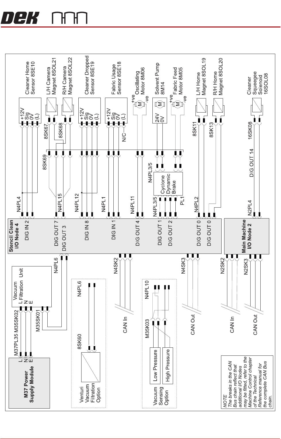
CYCLONE UNDER STENCIL CLEANER MODULE
ELECTRICAL SCHEMATIC
Chapter Issue 11, Feb 18 Technical Reference Manual 26.5
ELECTRICAL SCHEMATIC
Figure 26-2 Cyclone Schematic - Page 1
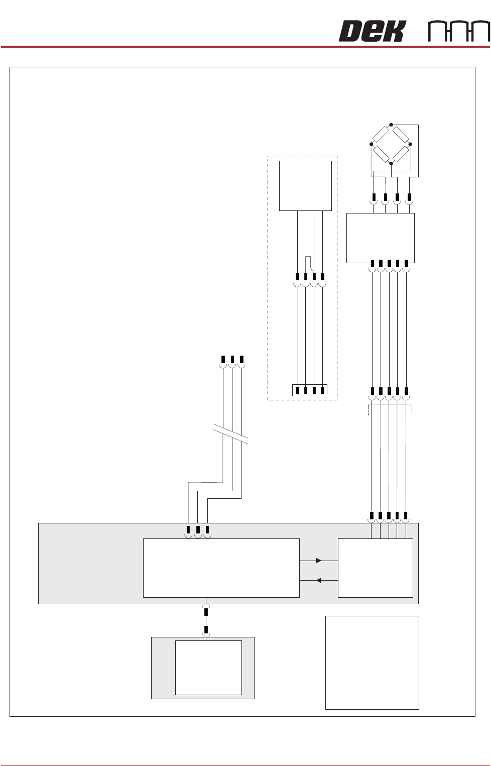
CYCLONE UNDER STENCIL CLEANER MODULE
ELECTRICAL SCHEMATIC
26.6 Technical Reference Manual Chapter Issue 11, Feb 18
Figure 26-3 Cyclone Schematic - Page 2
M36 Machine
Control Enclosure
PC
Motherboard
USB
NextMove ES
(I/O Node 1)
CAN_H
CAN_L
CAN GND
M36PL35
I/Ps
CAN Bus
O/Ps
9SK63
9PL64
Solvent
Load Cell
9SE26
NextMove
Interface
M36PL09
AN IN0 -
AN IN0 +
0V USR
+12V
-12V
Solvent
Level Amp
-V
+V
-IN
+IN
N2SK2
CAN
In
9SK69
Level +
Ext Service Panel
AGND
0V USR
+12V
-12V
NOTE
The breaks in the CAN
Bus chain reflect that
additional I/O Nodes
may be fitted, refer to the
Machine Control chapter
of the Technical
Reference manual for
the complete CAN Bus
chain.
9SE69
Solvent
Float
Sensor
969PL
9PL130
+V
0V
Output
E BY DEK Variation