192277 - Micron Technical Reference Volume 3.pdf - 第89页
BLUE UNDER SCREE N CLEANER MODULE ADJUSTMENTS AND SETTINGS Chapter Issue 10, Jul 16 Technical Reference Manual 24.9 8. Loosen the two securing screws at either end of the cleaner tray . 9. Adjust the cleaner tray until t…
BLUE UNDER SCREEN CLEANER MODULE
ADJUSTMENTS AND SETTINGS
24.8 Technical Reference Manual Chapter Issue 10, Jul 16
10. If adjustment is not required, go to Step 14.
11. Move the cleaner towards the rear of the machine until the vane securing
screws are accessible.
12. Loosen the vane securing screws, adjust the vane and re-tighten the
securing screws.
13. Repeat Steps 8 to 10.
14. Select Run Diagnost to energise the electromagnetic clamps.
15. Select Exit.
16. Select Exit.
17. Select Back.
Screen Cleaner
Height Adjustment
1. Select Unload Screen.
2. Open the front printhead cover.
3. Remove the stencil from the machine.
4. Using the calibration stencil, position the front edge of the stencil frame over
the under screen cleaner wipers.
5. Using feeler gauges ensure the gap between squeegee wipers and the
stencil frame is 3.25mm ±0.25mm.
6. If adjustment is not required, go to Step 11.
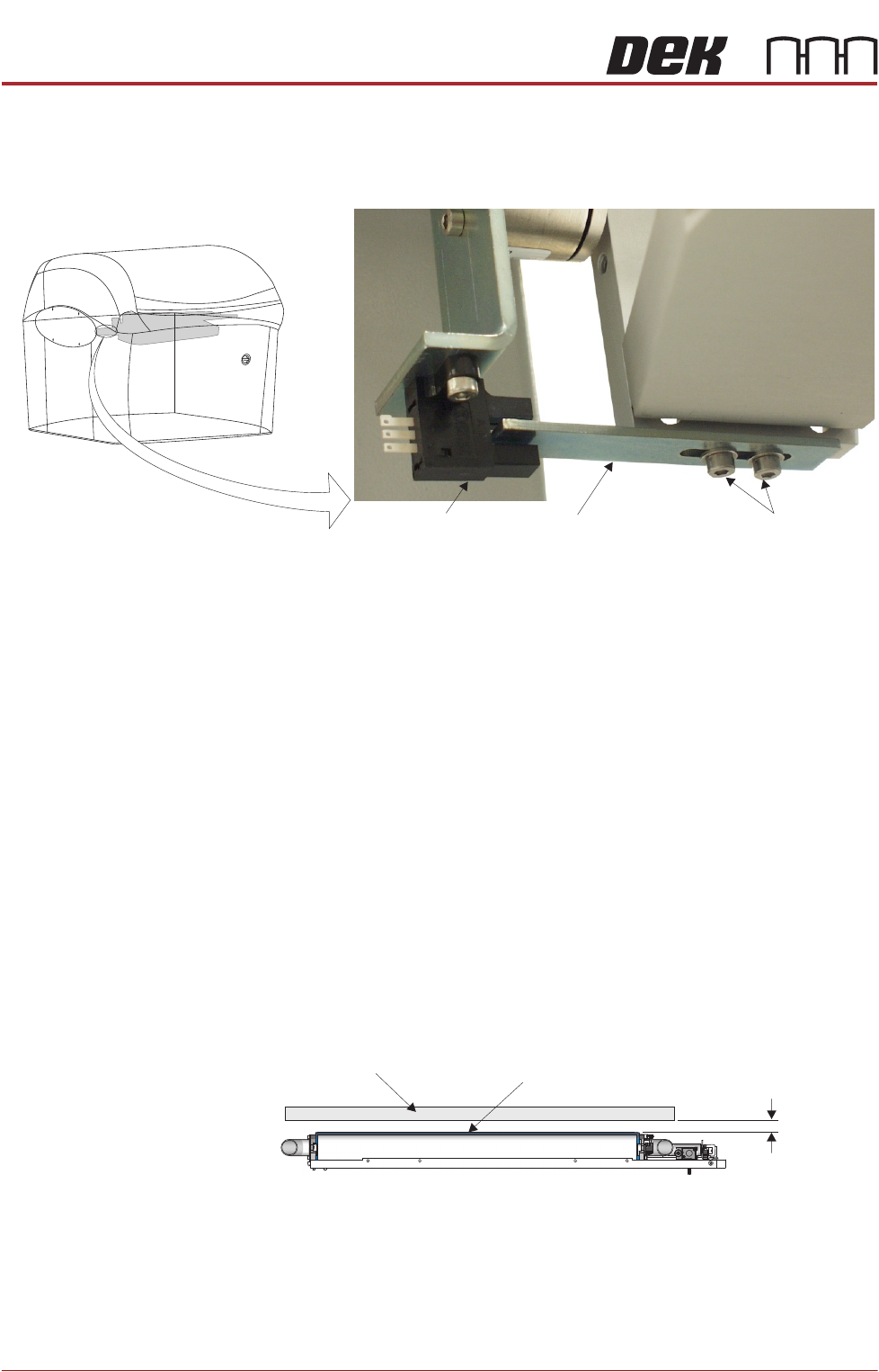
7. To gain access to cleaner securing screws move the underscreen cleaner
away from its home position.
View on Front of Machine
Vane Securing Screws
Home Sensor
Vane
Screen Frame
3.25mm
±0.25mm
Squeegee Wiper Assembly
View on Front of Machine
BLUE UNDER SCREEN CLEANER MODULE
ADJUSTMENTS AND SETTINGS
Chapter Issue 10, Jul 16 Technical Reference Manual 24.9
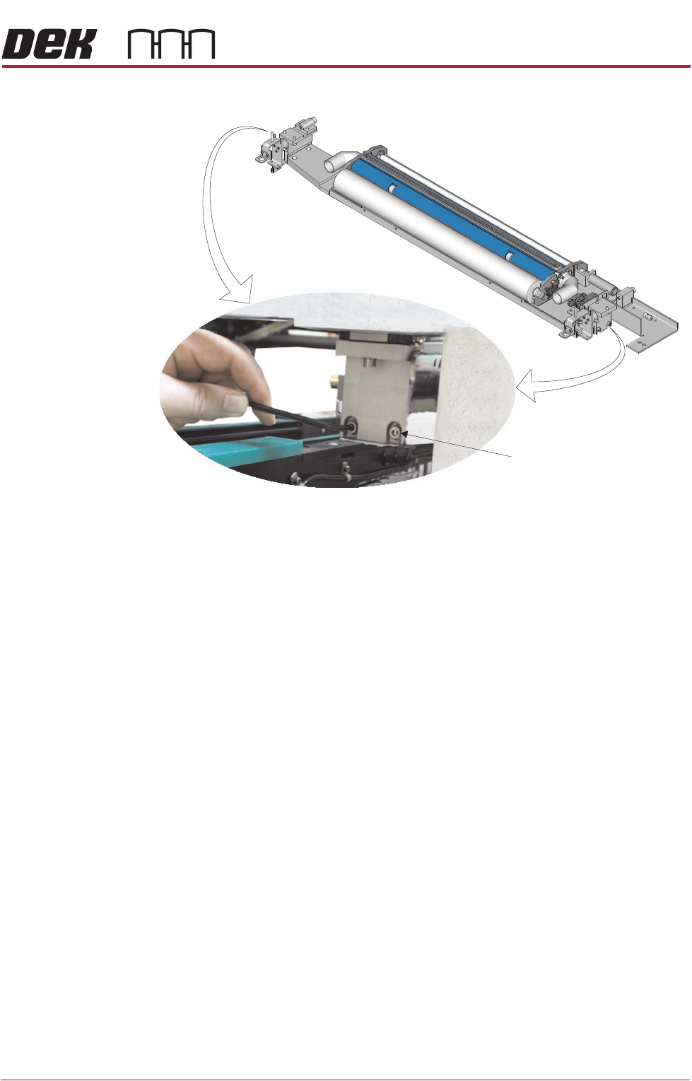
8. Loosen the two securing screws at either end of the cleaner tray.
9. Adjust the cleaner tray until the correct gap between the wipers and stencil
is achieved.
10. Tighten the securing screws and recheck the gap between the wipers and
stencil frame.
11. Refit the stencil.
12. Close the front printhead cover.
13. Press the System button.
14. Select Load Screen.
Securing Screw
(in 4 positions)
BLUE UNDER SCREEN CLEANER MODULE
ADJUSTMENTS AND SETTINGS
24.10 Technical Reference Manual Chapter Issue 10, Jul 16
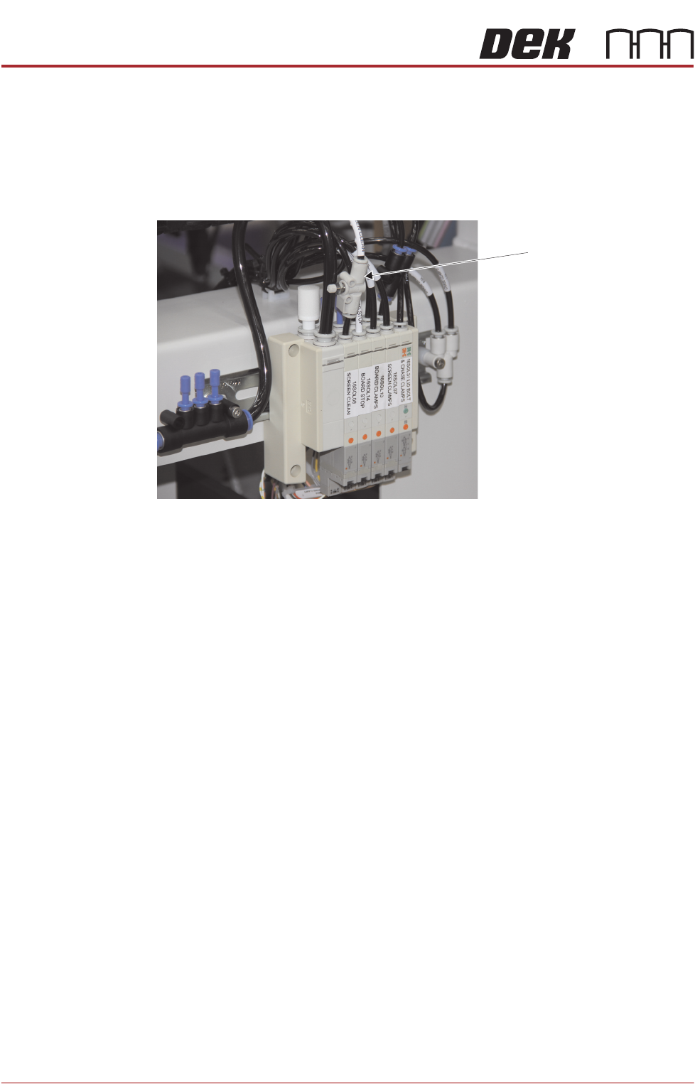
Lift Mechanism Air
Flow Controller
An in-line flow controller restricts the air flow to the cleaner lift mechanism to
prevent the cleaner from hitting the stencil with excessive speed.
The air flow should not need any adjustment unless replaced. Use the following
procedure to adjust the regulator:
1. Turn the thumbscrew on the lift mechanism air flow controller fully clockwise
to shut off the air supply.
2. Fit the calibration stencil into the machine.
3. Select Maintenance.
4. Select Diagnostics.
5. Use Next or Previous to highlight Screen Cleaner.
6. Select Select Module.
7. Ensure ‘Toggle Dry Wipe Blade’ is highlighted.
8. Select Run Diagnost.
9. Turn the thumbscrew on the lift mechanism air flow controller anticlockwise
until the cleaner mechanism raises fully.
10. Select Run Diagnost multiple times ensuring that the lift mechanism raises
fully (without struggling or slowing).
11. Select Exit.
12. Select Exit.
13. Select Back.
Lift Mechanism Air Flow
Controller
View on Rear of Machine