192277 - Micron Technical Reference Volume 3.pdf - 第217页
FOREIGN MACHINE INTERFACE MULTI-INTERFACE UNIT Chapter Issue 5, Aug 14 Technical Reference Manual 33.15 Figure 33-15 MIU Schematic N C N C N C N C N C N C Up l ine Board Fai l I /P Send Down l ine O/P 0V N C N C N C +12V…
FOREIGN MACHINE INTERFACE
MULTI-INTERFACE UNIT
33.14 Technical Reference Manual Chapter Issue 5, Aug 14
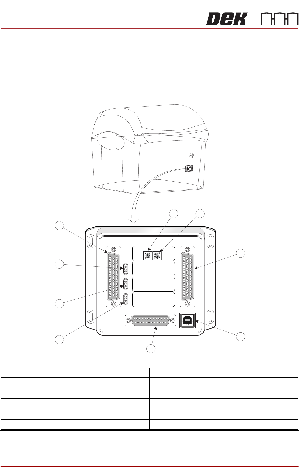
MULTI-INTERFACE UNIT
The Multi-Interface Unit (MIU) is a communications interface that allows DEK
Printing Machines to communicate with upline and downline board handlers.
The MIU is mounted on the services panel behind the rear panel of the machine
and connects to the M36 Machine Controller for its power supplies and input/
output signals.
Item Description Item Description
1 Upline Protocol Selection Switch 6 Output Indicator LED’s
2 Downline Protocol Selection Switch 7 Input Indicator LED’s
3 M1SK02 Downline Connector 8 Power Supply LED’s
4 M1SK04 USB Connector (not used) 9 M1SK01 Upline Connector
5 M1PL03 Power Supply Connector
M
1
S
K
1
M
1
SK1
U
P
L
I
N
E
UPL
INE
M
1
S
K
2
M1
S
K2
D
O
W
N
L
I
N
E
DOW
NLI
N
E
M
1
P
L
3
M
1PL
3
D
E
K
M
/
C
DEK
M/
C
M
1
S
K
4
M1S
K
4
D
E
K
U
S
B
DE
K
U
SB
+
1
2
V
+
1
2
V
+
2
4
V
+2
4V
+
2
4
V
S
W
+
2
4V
SW
S
E
N
D
U
P
L
I
N
E
S
E
ND
UP
LI
NE
S
E
N
D
D
O
W
N
L
I
N
E
SEN
D
DOWN
L
INE
C
O
N
T
R
O
L
I
N
CONTR
O
LIN
U
P
L
I
N
E
R
E
A
D
Y
U
PL
IN
E
R
EA
D
Y
D
O
W
N
L
I
N
E
R
E
A
D
Y
DOW
N
L
I
N
E
R
E
A
DY
C
O
N
T
R
O
L
O
U
T
C
O
NTR
O
LOUT
P
O
W
E
R
P
OWE
R
I
/
P
'
S
I
/
P
'
S
O
/
P
'
S
O
/P'
S
P
ROT
O
C
O
L
SE
L
E
C
T
ION
P
R
O
TO
C
OLSEL
E
C
T
I
O
N
U
P
UP
L
I
N
E
L
I
N
E
D
O
W
N
DOW
N
L
I
N
E
L
I
NE
MI
U
1
91
114MIU 191114
4
8
0
4
8
0
M1SK1
UPLINE
M1SK2
DOWNLINE
M1PL3
DEK M/C
M1SK4
DEK USB
+12V
+24V
+24V SW
SEND UPLINE
SEND DOWNLINE
CONTROL IN
UPLINE READY
DOWNLINE READY
CONTROL OUT
POWER
I/P'S
O/P'S
PROTOCOL SELECTION
UP
LINE
DOWN
LINE
MIU 191114
4
80
4
80
1 2
3
4
5
6
7
8
9
FOREIGN MACHINE INTERFACE
MULTI-INTERFACE UNIT
Chapter Issue 5, Aug 14 Technical Reference Manual 33.15
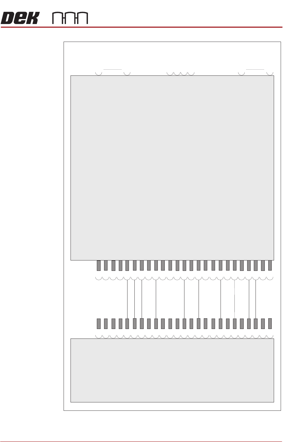
Figure 33-15 MIU Schematic
NC
NC
NC
NC
NC
NC
Upline Board
Fail I/P
Send Down
line O/P
0V
NC
NC
NC
+12V
+24V US
Down
line Ready
I/P
NC
NC
NC
Down
line Board
Fail O/P
NC
Send Upline O/P
Upline Ready
I/P
NC
+24V SW
NC
M36 Machine
Contro
l Enclosure
Multi-Interface
Unit (MIU)
Ready
to Receive
Downline O/P
Upline Board
Fail O/P
Send Down
line I/P
0V I/P
+12V
Down
line Board
Fail I/P
Send Upline I/P
Ready
to Receive
Upline O/P
NC
+24V SW
NC
M36SK04
01
02
03
04
05
06
07
08
09
10
11
12
13
14
15
16
17
18
19
20
21
22
23
24
25
01
01
02
03
04
05
50
06
07
08
09
10
11
01
12
02
13
03
14
04
15
16
17
18
19
20
21
01
22
23
24
25
50
M1PL03
M1SK01
M1SK04
M1SK02
NC
NC
NC
NC
NC
NC
NC
+24V US
NC
NC
NC
NC
NC
NC
Upline Connector
(see table)
USB Connector
(not used)
Downline Connector
(see table)
FOREIGN MACHINE INTERFACE
MULTI-INTERFACE UNIT
33.16 Technical Reference Manual Chapter Issue 5, Aug 14
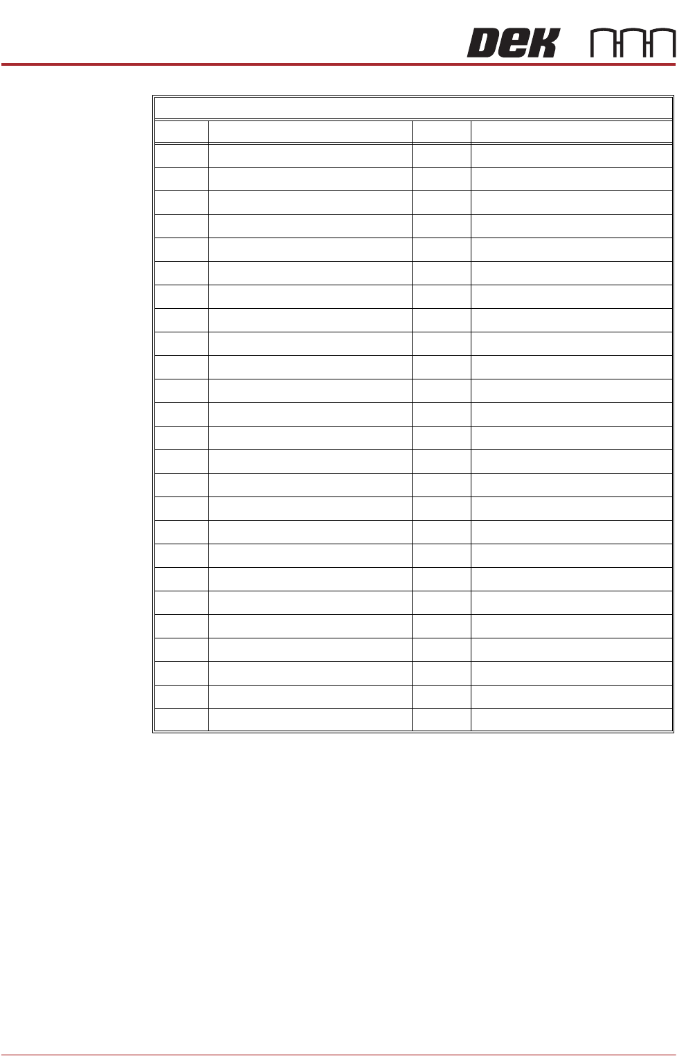
M1SK01 & M1SK02
Pin No. Function Pin No. Function
1 O/P 04a - Solid State Relay 26 I/P 03 - Opto Isolated
2 O/P 04b - Solid State Relay 27 NC
3 O/P 03a - Solid State Relay 28 NC
4 O/P 03b - Solid State Relay 29 O/P 02 - Lowside Driver
5 Links Pin 5 of M1SK01 & M1SK02 30 NC
6 Links Pin 6 of M1SK01 & M1SK02 31 NC
7NC 32+24V US
8 NC 33 +24V SW
9 I/P 04 - Opto Isolated 34 O/P 02a - Solid State Relay
10 I/P 02 - Opto Isolated 35 O/P 02b - Solid State Relay
11 NC 36 O/P 01a - Solid State Relay
12 O/P 04 - Lowside Driver 37 O/P 01b - Solid State Relay
13 O/P 03 - Lowside Driver 38 Links Pin 38 of M1SK01 & M1SK02
14 NC 39 NC
15 +24V US 40 NC
16 +24V SW 41 I/P +V for Optos 01 & 02
17 0V 42 I/P 01 - Opto Isolated
18 Links Pin 18 of M1SK01 & M1SK02 43 NC
19 Links Pin 19 of M1SK01 & M1SK02 44 NC
20 Links Pin 20 of M1SK01 & M1SK02 45 O/P 01 - Lowside Driver
21 Links Pin 21 of M1SK01 & M1SK02 46 NC
22 Links Pin 22 of M1SK01 & M1SK02 47 NC
23 NC 48 +12V
24 NC 49 +12V
25 I/P +V for Optos 03 & 04 50 0V