192277 - Micron Technical Reference Volume 3.pdf - 第15页
RAPID TRANSIT CONVEYOR (R TC) MODULE OVERVIEW Chapter Issue 4, Aug 14 Technical Reference Manual 22.3 The rapid transit conveyor (R TC) is a programmable width conveyor system which sets the rail width and transports boa…
RAPID TRANSIT CONVEYOR (RTC) MODULE
OVERVIEW
22.2 Technical Reference Manual Chapter Issue 4, Aug 14
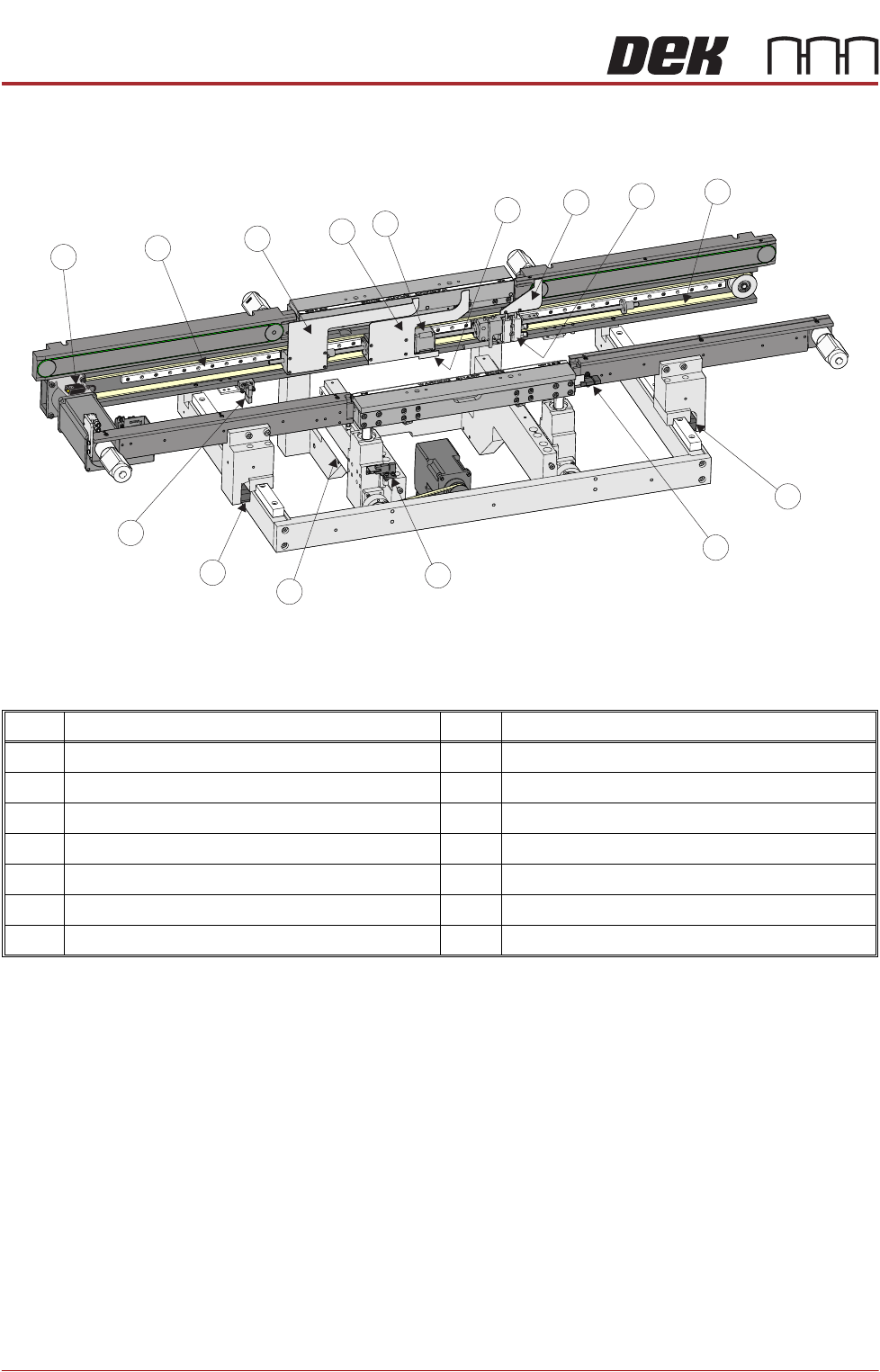
Figure 22-2 Rear View of RTC Rails
NOTE
Information given in this manual references a machine set up for left to right feed
direction. For machines designated right to left feed direction, contact ASM
Customer Support for assistance. Right to left feed machines are not a direct
mirror of the left to right machine the following exceptions relate:
1. In the circuit diagram, later in this chapter, Node 11 becomes Node 16.
2. In the circuit diagram, motor wiring designations are mirrored.
3. The motors are wired in the single direction mode, that is, left to right or right
to left; a machine wired for one direction cannot be wired for the opposite feed
direction.
Item Description Item Description
1 Transport Mechanism Drive Belt 8 Transport Mechanism Linear Guide
2 Pneumatic Rail Width Clamp (in 2 positions) 9 Outroad Vane
3 Rail Lifted Sensor 10 Board Stop Vane
4 Moving Rail Home Sensor 11 Inroad Vane Stepper Motor
5 Moving Rail Leadscrew (in 2 positions) 12 Transport Mechanism Home Vane
6 Transport Mechanism Home Sensor 13 Inroad Vane
7 Board at Right Sensor 14 Inroad Vane Lift Solenoid
1
2
2
3
4
5
6
7
8
9
10
11
12
13
14
RAPID TRANSIT CONVEYOR (RTC) MODULE
OVERVIEW
Chapter Issue 4, Aug 14 Technical Reference Manual 22.3
The rapid transit conveyor (RTC) is a programmable width conveyor system
which sets the rail width and transports boards through the machine using belts
and vanes. The system can accommodate up to three boards in the machine
at one time thereby reducing the machine cycle time.
The RTC system consists of three sections:
• Inroad Conveyor
•Print Station
• Outroad Conveyor
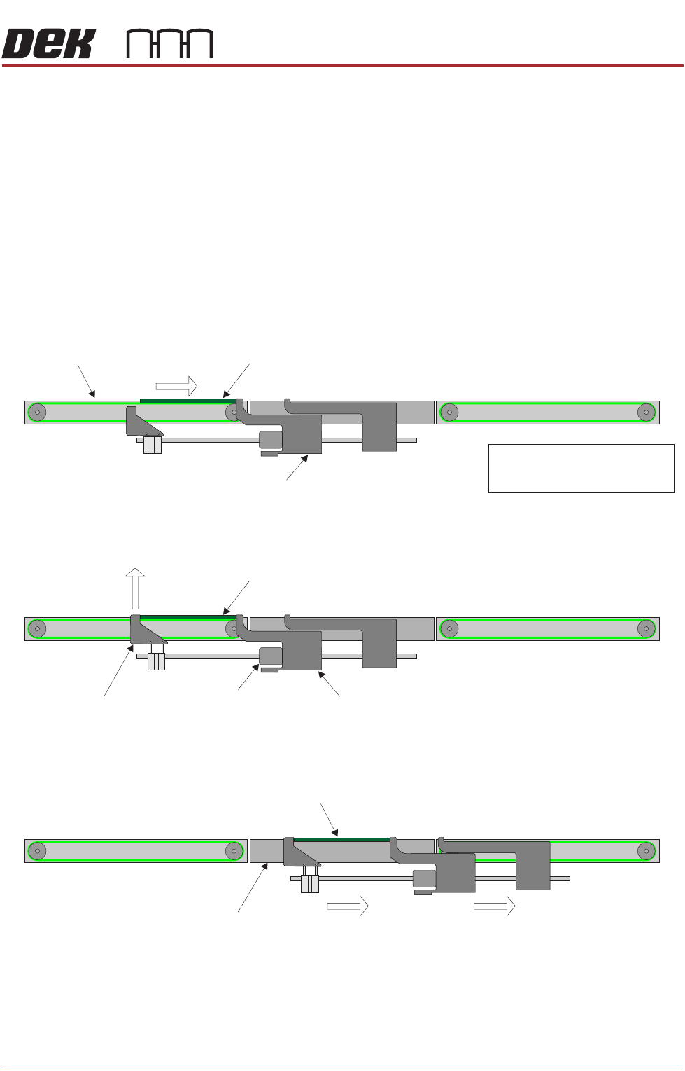
Using belts, Board 1 is transported to the end of the inroad conveyor where the
board is stopped by the board stop vane.
The inroad vane is raised and the vane stepper motor drives the inroad vane to
snug the board.
The transport mechanism moves the vanes placing the board in the centre of
the print station.
Board 1
Board Stop Vane
Inroad Conveyor
NOTE
1. Front rail removed for clarity.
2. Board direction Left to Right.
Vane Stepper Motor Board Stop VaneInroad Vane
Board 1
Board 1
Print Station
RAPID TRANSIT CONVEYOR (RTC) MODULE
OVERVIEW
22.4 Technical Reference Manual Chapter Issue 4, Aug 14
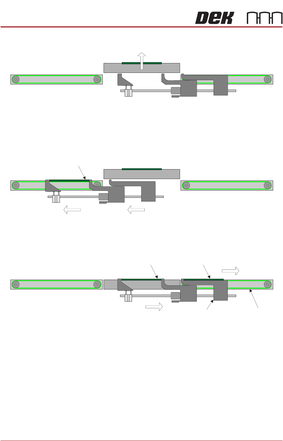
Board 1 is secured with the board clamps and the board is raised to print height.
Whilst at print height, the transport mechanism moves the vanes back to the
ready position; the inroad vane is driven away from the board stop vane and the
inroad vane is lowered. Board 2 enters the machine, the inroad vane is raised
and the vane stepper motor drives the inroad vane to snug the board.
At the end of the print stroke, the print station is lowered to transport height. The
transport mechanism moves Board 2 to the centre of the print station and the
outroad vane moves Board 1 on to the outroad conveyor.
The printed board is transported out of the machine on the outroad conveyor
using belts.
In the event of the downline machine being busy, Board 1 is stopped at the end
of the outroad conveyor by the outroad board stop. Board 2 is printed and Board
3 enters the machine and is held at the end of the inroad conveyor.
Board 2
Board 2 Board 1
Outroad ConveyorOutroad Vane