192277 - Micron Technical Reference Volume 3.pdf - 第193页
在线预览 192277 - Micron Technical Reference Volume 3.pdf PDF 文档。

BARCODE READER AND VERIFICATION AND TRACEABILITY
OVERVIEW - VERIFICATION AND TRACEABILITY
32.4 Technical Reference Manual Chapter Issue 10, Feb 17
OVERVIEW - VERIFICATION AND TRACEABILITY
Introduction Verification and traceability is a software tool that validates (verification) certain
items before printing and records data (traceability) to a file.
Purpose Verification ensures that the product and the consumable items used in the print
process match the information stored in the product file.
At the end of each print cycle, verification information is written to the traceability
file. This information may be used to trace particular batches of a product run
and identify all the consumables used for that batch.
Operation At the beginning of a product run, the operator is required to verify the consum-
ables fitted to the machine. This is achieved by either scanning the barcode
using the handheld barcode reader or entering the identity information using the
keyboard.
During the print run, the product is automatically scanned by the remote
barcode reader located on the input conveyor; the data scanned in, is stored for
traceability with the print data. Each board is checked against the information
stored in the product file.
When a consumable item is replaced on the machine, the operator is requested
to verify the item by entering the identity of the item. This is checked against
the information stored in the product file before the print cycle can continue.
BARCODE READER AND VERIFICATION AND TRACEABILITY
REPLACEMENT PROCEDURES
32.6 Technical Reference Manual Chapter Issue 10, Feb 17
REPLACEMENT PROCEDURES
These procedures detail how to fit and set up the equipment.
Fitting the Remote
Barcode Reader
1. Select Shut Down and switch the mains isolator to OFF.
2. Securely mount the remote barcode reader on it’s mounting stand.
3. Mount the unit onto the upline conveyor, ensuring that the reader is in a
position to read the barcode on the product.
NOTE
Because conveyor systems vary, the remote barcode reader is supplied on
a fully adjustable mounting stand. This stand should be secured in a suitable
location on the input side of the conveyor.
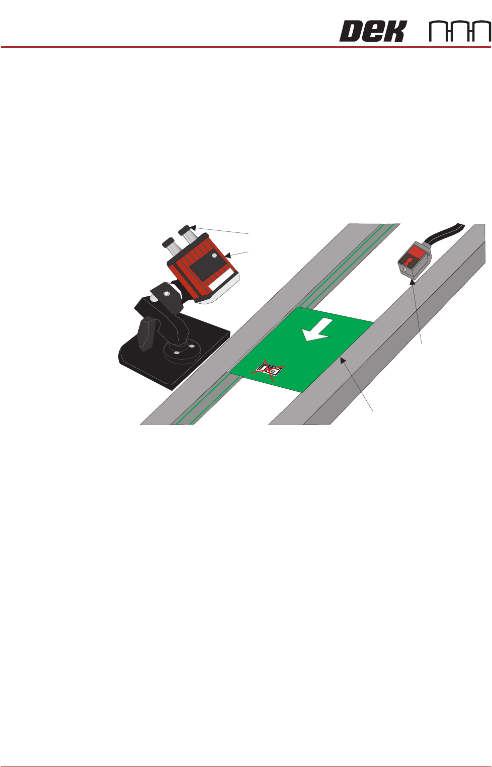
4. Fit the trigger sensor just before the reader (a Velcro fastener is used for
attaching it).
NOTE
The leading edge of the incoming board, triggers the remote barcode reader
into activation, enabling it to read the barcode on the board. A crosshair
provides an alignment check to target the label in the correct location.
5. Remove the printer’s rear panel to gain access to the PC.
NOTE
Type 4 Machine PC modules are located and accessed from the front of the
machine.
6. The Power and Signal (Barcode Reader) and the Trigger Sensor cables are
combined into one loom. Route the loom from the conveyor, under the DEK
printer exiting at the rear.
7. Attach the D type connector to the USB conversion cable - 9-pin D type
(USB to Serial (RS232)).
8. Power up the printer at the mains isolator.
9. On the MMI, select Start.
10. Select Run.
11. Type ‘pnpon’ in the command box.
Product with Barcode Label
Trigger Sensor
Barcode Reader
Power and Signal
Board Feed Direction