192277 - Micron Technical Reference Volume 3.pdf - 第91页
BLUE UNDER SCREE N CLEANER MODULE REPLACEMENT PROCEDURES Chapter Issue 10, Jul 16 Technical Reference Manual 24.11 REPLACEMENT PROCE DURES Solvent Pump W ARN ING SOL VENT SPRA Y . THE UNDERSCREEN CLEANER SPRA YS A FINE J…
BLUE UNDER SCREEN CLEANER MODULE
ADJUSTMENTS AND SETTINGS
24.10 Technical Reference Manual Chapter Issue 10, Jul 16
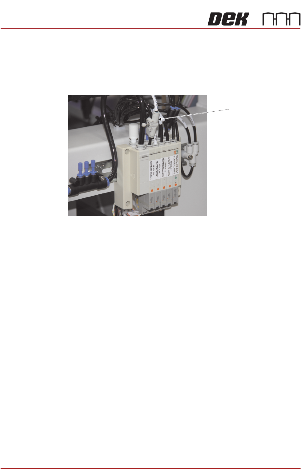
Lift Mechanism Air
Flow Controller
An in-line flow controller restricts the air flow to the cleaner lift mechanism to
prevent the cleaner from hitting the stencil with excessive speed.
The air flow should not need any adjustment unless replaced. Use the following
procedure to adjust the regulator:
1. Turn the thumbscrew on the lift mechanism air flow controller fully clockwise
to shut off the air supply.
2. Fit the calibration stencil into the machine.
3. Select Maintenance.
4. Select Diagnostics.
5. Use Next or Previous to highlight Screen Cleaner.
6. Select Select Module.
7. Ensure ‘Toggle Dry Wipe Blade’ is highlighted.
8. Select Run Diagnost.
9. Turn the thumbscrew on the lift mechanism air flow controller anticlockwise
until the cleaner mechanism raises fully.
10. Select Run Diagnost multiple times ensuring that the lift mechanism raises
fully (without struggling or slowing).
11. Select Exit.
12. Select Exit.
13. Select Back.
Lift Mechanism Air Flow
Controller
View on Rear of Machine

BLUE UNDER SCREEN CLEANER MODULE
REPLACEMENT PROCEDURES
Chapter Issue 10, Jul 16 Technical Reference Manual 24.11
REPLACEMENT PROCEDURES
Solvent Pump
WARNING
SOLVENT SPRAY. THE UNDERSCREEN CLEANER SPRAYS A FINE JET OF
SOLVENT SOLUTION ON TO THE CLEANER. APPROVED PROTECTIVE
CLOTHING SHOULD BE WORN.
CAUTION
SOLDER PASTE AND SOLVENTS. WHEN USING OR HANDLING ANY SOLDER
PASTE OR SOLVENT FORMULATION THE MANUFACTURERS’ SAFETY DATA
SHEETS MUST BE STRICTLY ADHERED TO.
MANDATORY
TOXIC CHEMICALS MAY BE PRESENT. SAFETY GLOVES MUST BE WORN.
MANDATORY
TOXIC CHEMICALS MAY BE PRESENT. EYE PROTECTION MUST BE WORN.
1. Open the printhead front cover and remove the stencil.
2. Move the print carriage to the rear.
3. Power down the printer and fit a lock to the mains isolator lock out.
4. Disconnect the solvent feed tube on the right hand side bracket.
5. Disconnect the electrical connector on the right hand side of the pump body.
6. Remove 2 M3 x 6 screws holding the pump mounting bracket on the
underside of the cleaner tray.
7. Remove the pump.
8. Fit the replacement pump and secure using the two M3 screws.
9. Refit the feed tube and the electrical connector.
NOTE
Ensure that the tubing is routed such that it is not stressed or kinked.
10. Pull the cleaner to the front of the machine such that it engages the magnets.
11. Remove the lock from the mains isolator.
12. Turn the mains power ON.
13. Close the printhead front cover.
14. Select Diagnostics.
15. Press the System switch.
16. Select the Camera Axes.
17. Select Home Camera X Axis and select Home Camera Y Axis to home

BLUE UNDER SCREEN CLEANER MODULE
REPLACEMENT PROCEDURES
24.12 Technical Reference Manual Chapter Issue 10, Jul 16
the camera axes.
18. Select Exit.
19. Select the Screen Cleaner module page.
20. Ensure that all functions within screen cleaner diagnostics operate correctly
and that there are no leaks from the feed tubing.
21. Select Exit.
22. Select Exit.