192277 - Micron Technical Reference Volume 3.pdf - 第135页
RISING TABLE MODULE - STYLE 1 ADJUSTMENTS AND SETTINGS Chapter Issue 9, Aug 14 Technical Reference Manual 27.5 16. Use Next or Previous to hig hlight Rising T able . 17. Select Select Module . 18. Ensure Home Rising T ab…
RISING TABLE MODULE - STYLE 1
ADJUSTMENTS AND SETTINGS
27.4 Technical Reference Manual Chapter Issue 9, Aug 14
ADJUSTMENTS AND SETTINGS
Rising Table Home Setting
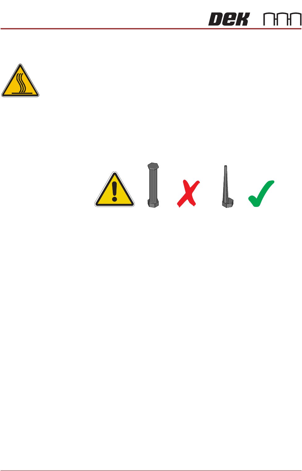
WARNING
HOT SURFACES. THE SURFACE OF THIS COMPONENT OR SURROUNDING
AREA MAY BECOME HOT DURING PROLONGED OPERATION. CARE TO BE
TAKEN WHEN WORKING IN THE VICINITY OF THIS COMPONENT.
NOTE
1. 1. For MTR rail systems, the rails are fitted with a modular mid section.
MTR rails are deeper than the RS systems. The magnetic tooling pins
supplied with RS rail systems must not be used with the MTR rail system,
as this may cause equipment damage.
2. 2. Due to the deeper rails being present on MTR systems, the rising table
height settings are different.
3. 3. For rising table home setting on a dual lane machine, refer to the Dual
Lane Module chapter.
4. The Rapid Throughput Conveyor (RTC) printer option has its rising table
home height 10mm lower than that of a standard printer (198mm to
200mm).
1. Select Open Cover Commands.
2. Select Carriage To Rear.
3. Select Unload Screen.
4. Open the front printhead cover.
5. Move the screen so that the rear edge is further forward than the rear edge
of the manual tooling plate.
6. Close the front printhead cover.
7. Press the System button.
8. Select Back.
9. Select Maintenance.
10. Select Diagnostics.
11. Use Next or Previous to highlight Screen Change.
12. Select Select Module.
13. Ensure Toggle Screen Clamps is highlighted.
14. Select Run Diagnost.
15. Select Exit.
RISING TABLE MODULE - STYLE 1
ADJUSTMENTS AND SETTINGS
Chapter Issue 9, Aug 14 Technical Reference Manual 27.5
16. Use Next or Previous to highlight Rising Table.
17. Select Select Module.
18. Ensure Home Rising Table is highlighted.
19. Select Run Diagnost.
20. Remove the left hand side safety cover to gain access to the rear of the
screen and rising table.
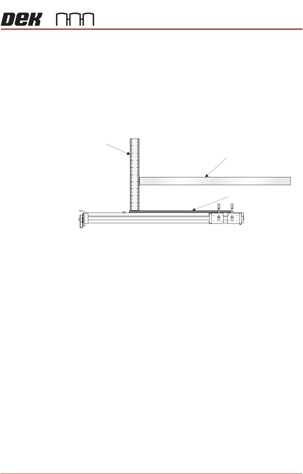
21. Place a steel rule between the rear of the screen and the rear frame of the
Chase/ASM ensuring the end of the steel rule is in contact with the manual
tooling plate of the rising table.
22. Check that the distance from the top of the manual tooling plate to the
underside of the screen for RS rails is 209mm ±1mm.
23. Check that the distance from the top of the manual tooling plate to the
underside of the screen for MTR rails is 233mm ±1mm.
24. If adjustment is not required, remove the steel rule and go to Step 31.
View on Left Hand Side of Machine
Steel Rule
Screen
Manual Tooling Plate
RISING TABLE MODULE - STYLE 1
ADJUSTMENTS AND SETTINGS
27.6 Technical Reference Manual Chapter Issue 9, Aug 14
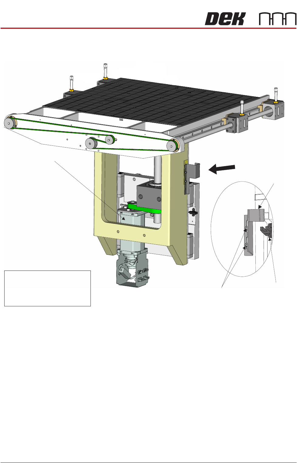
25. From the left hand side of the machine, slacken the two home vane securing
screws.
26. If the rising table needs to be higher, move the home vane downwards and
secure the two home vane securing screws.
27. If the rising table needs to be lower, move the home vane upwards and
secure the two home vane securing screws.
28. Remove the steel rule from the machine.
29. Select Run Diagnost.
30. Repeat Steps 21 to 29.
31. Refit the safety cover.
32. Select Exit.
33. Select Exit.
34. Select Back.
Rising Table Motor
A
View on Rear Right of Rising Table
Rising Table
Home Sensor
VaneHome
Home Vane
Securing Screws
View on Arrow A
NOTE
The rising table home position is
lower with Modular Transport Rail
system therefore, the home vane
has a smaller vane.