192277 - Micron Technical Reference Volume 3.pdf - 第146页
RISING TABLE MODULE - STYLE 2 ADJUSTMENTS AND SETTINGS 28.4 Techncial Reference Manual Chapter Issue 3, Feb 18 ADJUSTMENTS AND SETTINGS Rising T able Home Setting W ARN ING HOT SURF ACES. THE SURF ACE OF TH IS COMPONENT …
RISING TABLE MODULE - STYLE 2
ELECTRICAL SCHEMATIC
Chapter Issue 3, Feb 18 Technical Reference Manual 28.3
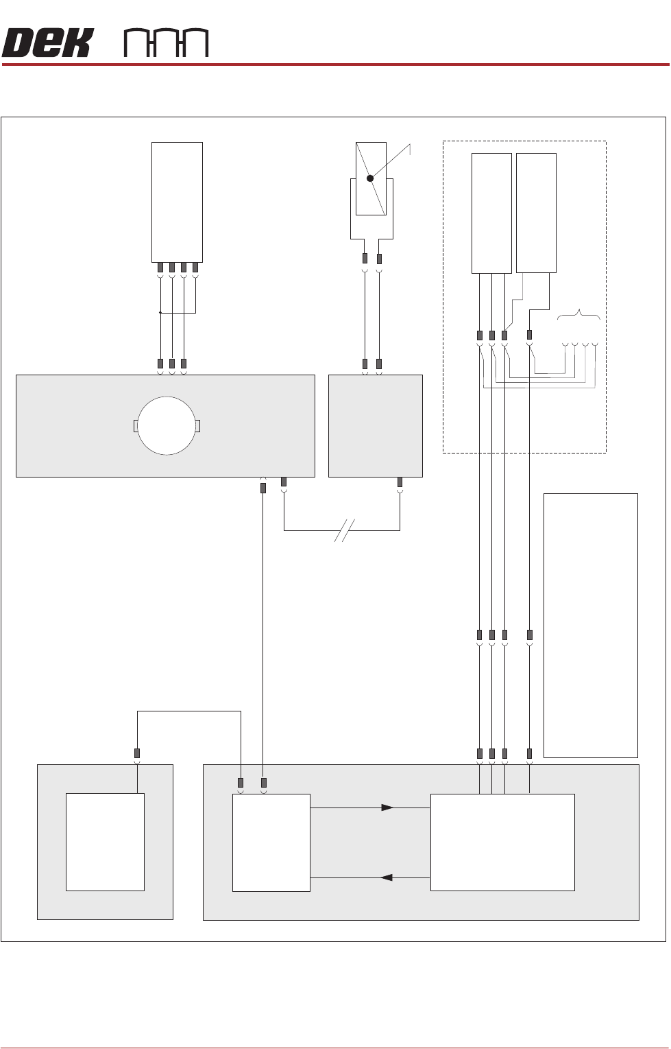
ELECTRICAL SCHEMATIC
NextMove ES
(I/O Node 1)
X5
Machine Control Enclosure
NextMove
Interface Card
X4
I/Ps O/Ps
Remote Board Stop (optional)
If Remote Board Stop is
Right Hand Side Configured
Board Stop Extended
Sensor (10SE25)
Board At Stop
Sensor (10SE26)
8SK05(L)
8SK05(R)
+12V
0V
0V
Sig
Sig
USB
M36PL11
BPL6A
BSK6
M36PL28
3PL35
Motherboard
Machine PC
NOTES
The breaks in the CAN Bus chain reflect that additional1.
I/O Nodes may be fitted, refer to Machine Control
chapter for the complete CAN Bus chain.
2. Camera Board Stop sensors are detailed in the Camera
chapter of this manual.
3. Rail Lift sensors are detailed in the respective Transport
Rails chapter of this manual.
Rising Table
Home Sensor
(8SE1)
N6 4PL
(8M1)
Rising Table Motor
Servo Node 6
CAN In
N6 3PL
M36PL35
CAN Bus
(see Note)
Main Machine
I/O Node 2
Board Stop
(16SOL14)
Manual Operation
16SK14
N2PL4
N2SK2
M
CAN Out
N6SK2
+24V
SIG
0V
(L)
RISING TABLE MODULE - STYLE 2
ADJUSTMENTS AND SETTINGS
28.4 Techncial Reference Manual Chapter Issue 3, Feb 18
ADJUSTMENTS AND SETTINGS
Rising Table Home Setting
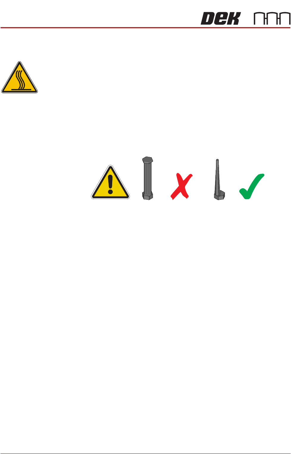
WARNING
HOT SURFACES. THE SURFACE OF THIS COMPONENT OR SURROUNDING
AREA MAY BECOME HOT DURING PROLONGED OPERATION. CARE TO BE
TAKEN WHEN WORKING IN THE VICINITY OF THIS COMPONENT.
NOTE
1. 1. For MTR rail systems, the rails are fitted with a modular mid section.
MTR rails are deeper than the Standard system. The magnetic tooling pins
supplied with Standard rail systems must not be used with the MTR rail
system, as this may cause equipment damage.
2. 2. Due to the deeper rails being present on MTR systems, the rising table
height settings are different.
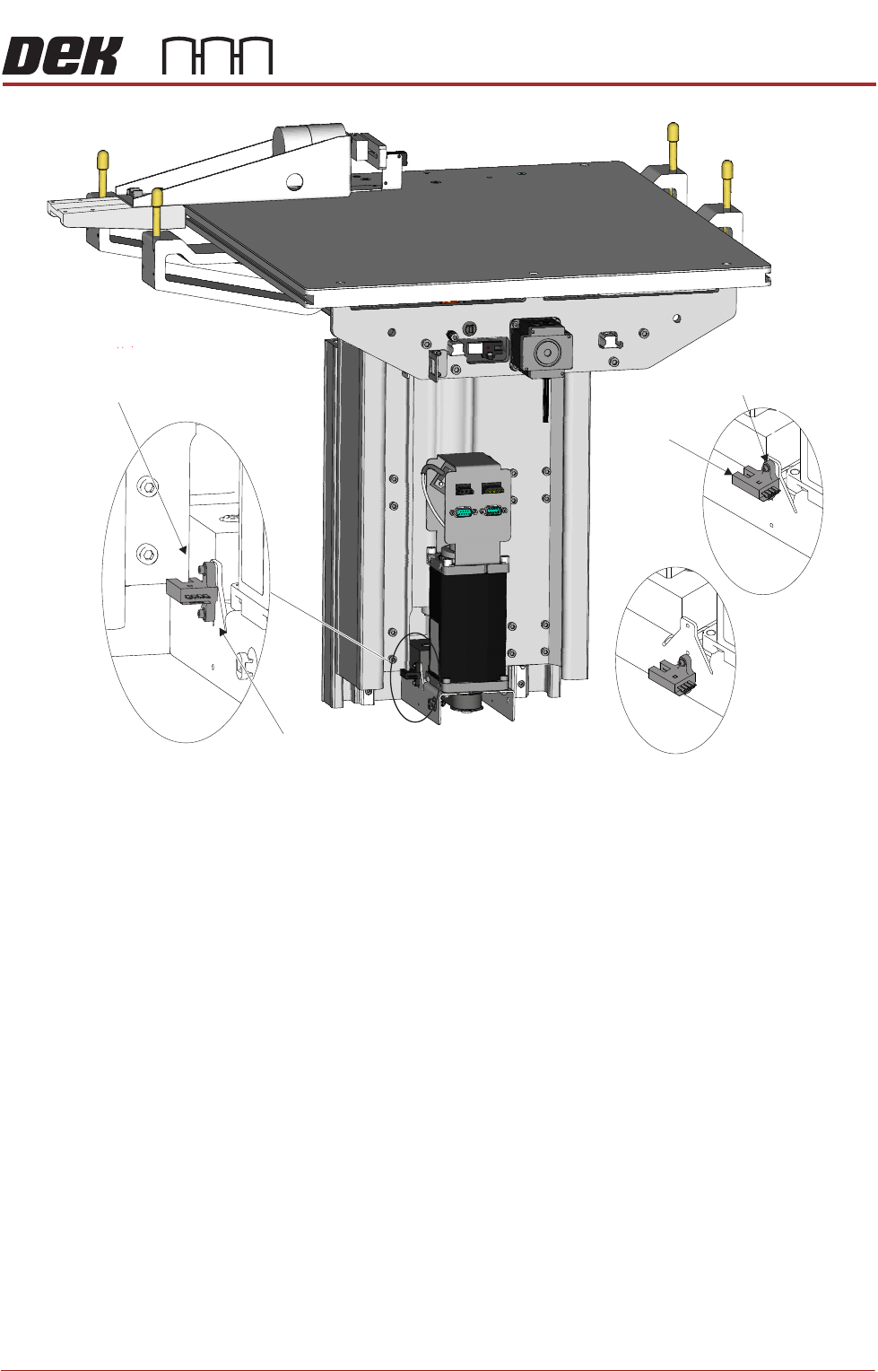
Two home sensor positions are available:
• Standard Home position (upper position)
• MTR Home position (lower position)
The procedure for changing the home sensor position should only be carried
out when switching between Standard and MTR options.
1. Power down the printer and fit a lock to the mains isolator lock out.
2. Gain access to the rising table motor.
3. Locate the home sensor.
4. Using a 2.5mm Allen key, undo the two home sensor securing screws.
5. Position the home sensor in the required location.
6. Fasten and tighten the two securing screws.
7. Turn the mains power ON.
8. Carry out the following calibrations:
• Vision Height, Camera System Module chapter refers
• Print Height, Calibrations section of this chapter refers
RISING TABLE MODULE - STYLE 2
ADJUSTMENTS AND SETTINGS
Chapter Issue 3, Feb 18 Technical Reference Manual 28.5
View on Rear of Rising TableLeft
Standard
MTR
Home Vane
Home Sensor
Home Sensor
Home Sensor
Securing Screws