192277 - Micron Technical Reference Volume 3.pdf - 第153页
BOARD SUPPORT TO OLING MODULE INTRODUCTION Chapter Issue 7, Jan 15 Technical Reference Manual 29.1 CHAPTER 29 BOARD SUPPOR T TOOLING MODULE INTRODUCTION The board support tooling module includes the following: • Manual T…

RISING TABLE MODULE - STYLE 2
TEST CYCLES
28.10 Techncial Reference Manual Chapter Issue 3, Feb 18
BOARD SUPPORT TOOLING MODULE
INTRODUCTION
Chapter Issue 7, Jan 15 Technical Reference Manual 29.1
CHAPTER 29 BOARD SUPPORT TOOLING MODULE
INTRODUCTION The board support tooling module includes the following:
• Manual Tooling Plate
• Tooling Options
Manual Tooling
Plate
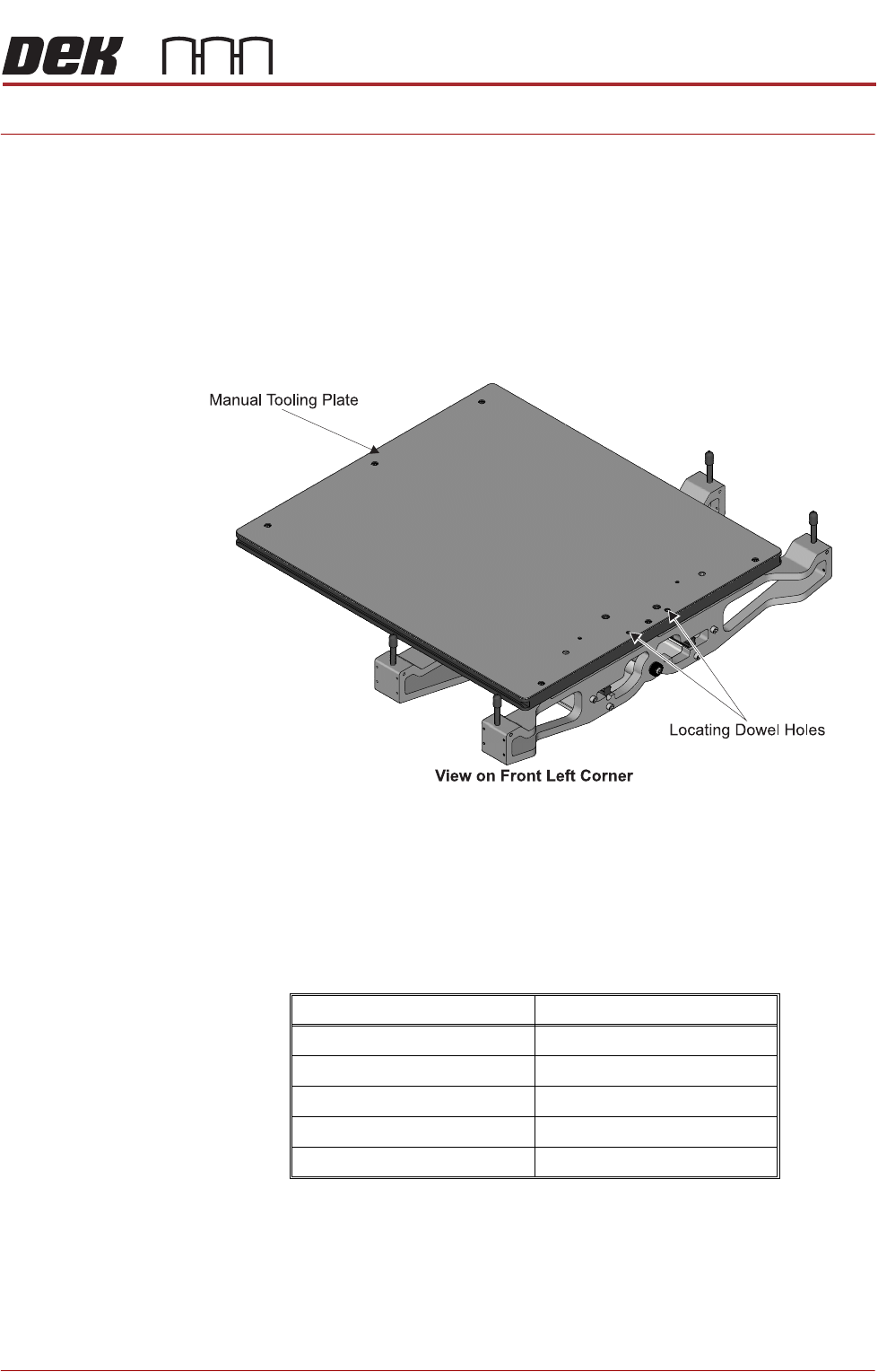
The manual tooling plate is the basic tooling module fitted to the machine rising
table. There are various tooling options which attach to the manual tooling plate
either by dowel pins or magnetically.
Figure 29-1 Manual Tooling Plate
Tooling Options NOTE
Do not leave unused tooling on the rising table in the area behind the rear rail.
If any object is left on the rising table outside the board printing area, it could
collide with the camera carriage as the rising table moves to print height.
The following table shows how the tooling options are fitted to the tooling plate:
Tooling Fixing
Magnetic Support Pillars Magnetic
Vacuum Box Tooling Dowel Pins
Dedicated Tooling Plate Dowel Pins and Magnetic
ProFlow Stencil Support Magnetic
Grid-Lok Tooling Magnetic
BOARD SUPPORT TOOLING MODULE
MAGNETIC SUPPORT PILLARS
29.2 Technical Reference Manual Chapter Issue 7, Jan 15
MAGNETIC SUPPORT PILLARS
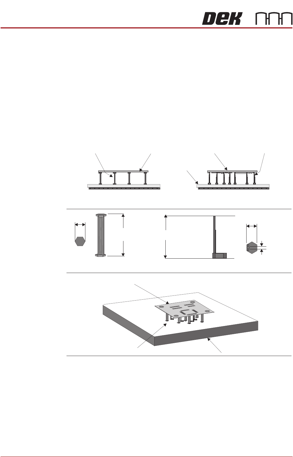
The magnetic support pillars are positioned on the manual tooling plate by the
operator. These pillars can be positioned anywhere under the board to provide
board support. The base of each type has a permanent magnet installed. There
are two types of support pillars available:
• Flat-top pillars (19mm) for supporting boards which are not populated on
the underside.
• Pin-top (Offset) pillars (4mm) for supporting boards which are populated
on the underside. The pillars are positioned so that they fit between the
components on the underside of the board. They have a 4mm top dimen-
sion.
Figure 29-2 Magnetic Support Pillars
Flat-top Pillars used on
Unpopulated Board
Tooling Plate
Offset Pillars used on
Populated Board
Populated BoardFlat-top Pillars Offset PillarsUnpopulated Board
Board
Magnetic Pillars
Tooling Plate
19mm
81mm
(nominal)
81mm
(nominal)
19mm Dia.
Flat-top Pillar Dimensions
Pin-top Pillars Dimensions
4mm Dia.