192277 - Micron Technical Reference Volume 3.pdf - 第186页
AIR IONI ZER MODULE REPLACEMENT PROCEDURES 31.6 Technical Reference Manual Chapter Issue 5, Aug 14 REPLACEMENT PROCE DURES W ARN ING COMPRESSED AIR. COMPRESSED AIR SH OULD NEVER IMPINGE UPON THE BODY . PORTS, P IPES, ETC…
AIR IONIZER MODULE
ADJUSTMENTS AND SETTINGS
Chapter Issue 5, Aug 14 Technical Reference Manual 31.5
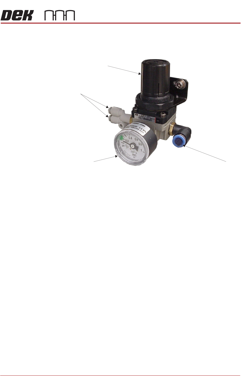
Air Regulator The air regulator sets the air pressure to the air ionizer and must be set to
0.20MPa (2.0 bar). To adjust the air pressure, use the following procedure:
1. Pull the regulator control valve upwards to unlock it.
2. Turning the regulator control valve clockwise to increase the pressure or
anti-clockwise to decrease the pressure, set the pressure to 0.20MPa (2.0
bar).
3. With the pressure set, push the regulator control valve downwards to lock it.
Regulator Control Valve
Air Out to Air Ionizer
Pressure Gauge Air In
View on Air Regulator
AIR IONIZER MODULE
REPLACEMENT PROCEDURES
31.6 Technical Reference Manual Chapter Issue 5, Aug 14
REPLACEMENT PROCEDURES
WARNING
COMPRESSED AIR. COMPRESSED AIR SHOULD NEVER IMPINGE UPON THE
BODY. PORTS, PIPES, ETC MUST NEVER BE BLOCKED BY HAND. BEFORE
CONNECTING OR DISCONNECTING ANY PNEUMATIC COMPONENTS, ENSURE
THE COMPRESSED AIR SUPPLY HAS BEEN DISSIPATED AND DISCONNECTED
FROM THE MACHINE.
WARNING
LETHAL VOLTAGE. DANGEROUS VOLTAGES EXIST IN THIS EQUIPMENT.
ENSURE ALL ELECTRONIC COVERS AND MAIN MACHINE COVERS ARE FITTED
BEFORE OPERATING THIS EQUIPMENT.
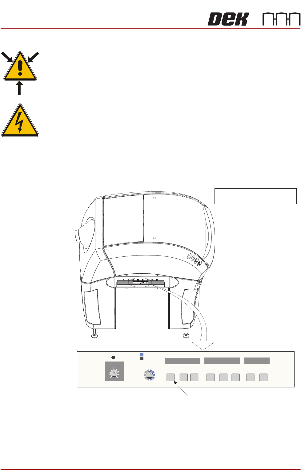
Stain Detection The air ionizer monitors the quantity of ions generated by itself, if the level
deteriorates, the needle check (NDL Check) indicator flashes on the air ionizer
control panel. The control panel is visible through the slot in the left hand safety
cover.
Figure 31-1 Air Ionizer Control Panel
If the NDL Check indicator flashes, one or more of the fourteen electrodes (7
cartridges on the array, each cartridge has two electrodes) may be dirty or faulty.
It is recommended that the electrodes are cleaned. If the ion level alarm
indicator continues to flash, replace all the electrodes. An electrode needle
cleaning kit is available contact ASM Customer Support for details.
0123456789
ABCDEF
0123456789
ABCDEF
0123456789
ZERO
FREQIDI/O MONITOR
OFF
TERM
ON
TERM
ON
I.C.C. CONDLEVEL
ION MONITOR
ION
ALM RC
+
-
View on Left Side of Machine
NOTE
Safety cover removed for clarity.
Needle Check Indicator
H
L
M
H
M
L
MANUAL
AUTO
MANUAL
LEVEL
Zero
Adjust
NDL
CHECK
+
SNSRSNSR
OK
MAINHV
-
ALARM
ION POWER
2
3
7
8
FREQ SELECT
6
7
8
5
4
3
6
7
5
4
3
AIR IONIZER MODULE
REPLACEMENT PROCEDURES
Chapter Issue 5, Aug 14 Technical Reference Manual 31.7
Use the following procedures to clean and replace the electrodes if necessary.
Electrode Cleaning 1. Ensure that the machine is isolated from mains electrical supply and the air
supply is disconnected.
2. Remove the left hand side safety cover from the machine to gain access to
the air ionizer.
3. Locate the row of electrode cartridges on the base of the ionizer.
NOTE
The mounting brackets angle the ionizer toward the inside of the printer by
approximately 45 degrees. The units should be accessible without removing
machine covers.
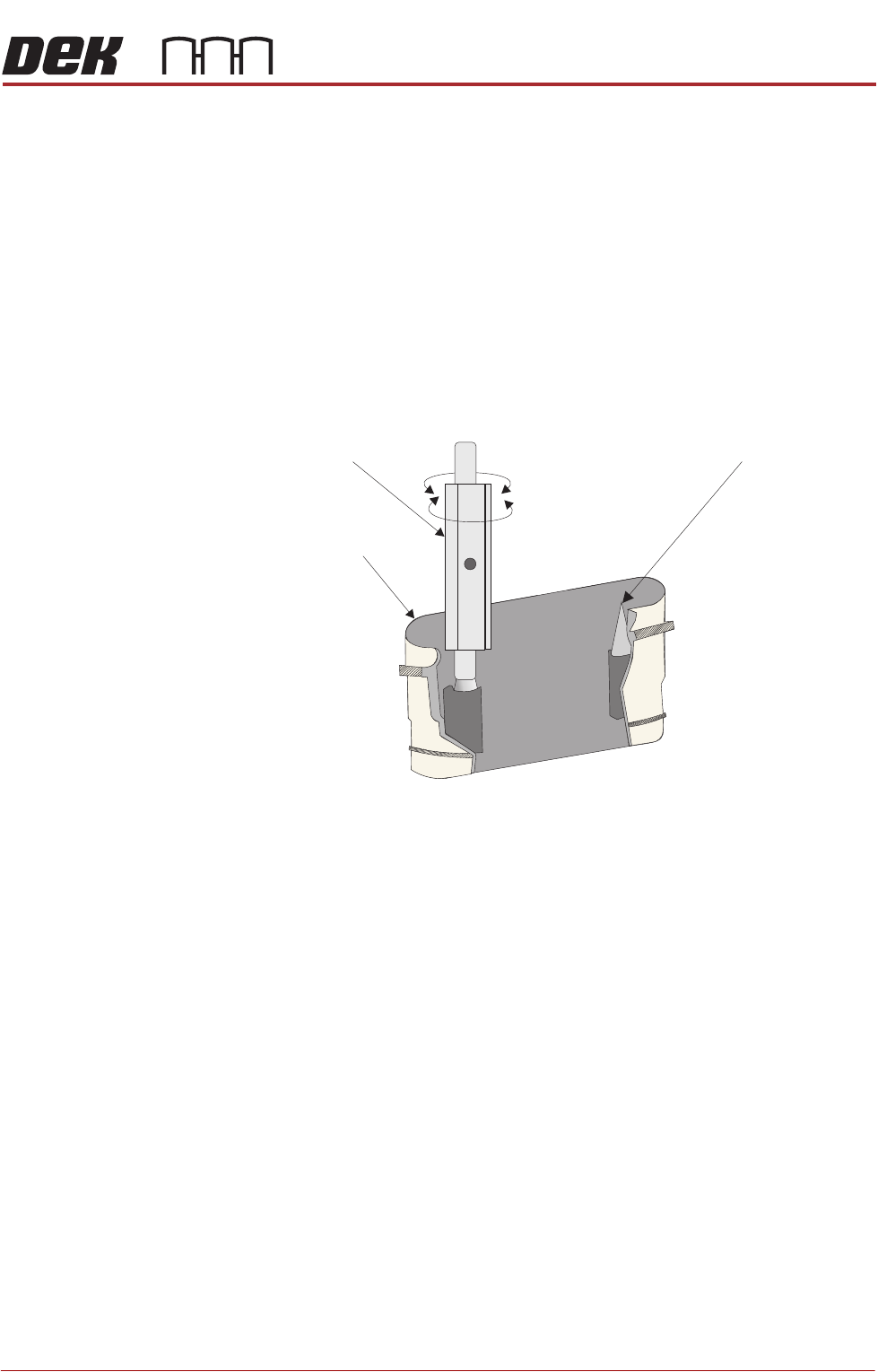
4. Using the electrode cleaner, clean the first electrode pair.
5. Repeat for the rest of the electrodes.
6. Refit the left hand side safety cover.
Electrode Cartridge
Replacement
When replacing an electrode due to wear, all the electrodes must be changed
at the same time for the air ionizer to work efficiently. To change the electrode
cartridges, use the following procedure:
1. Ensure that the machine is isolated from mains electrical supply and the air
supply is disconnected.
2. Remove the left hand side safety cover to gain access to the air ionizer.
Electrode Cartridge
Needle Tip
Twist
Electrode Cleaner
Electrode Holder (cut-away) Showing Electrode Needle Tips to be Cleaned