192277 - Micron Technical Reference Volume 3.pdf - 第30页
RAPID TRANSIT CONVEYOR (RTC) MODULE ADJUSTMENTS AND SETTINGS 22.18 Technical Reference Manual Chapter Issue 4, Aug 14 prompted. 14. Select Set Rail Board Width Calibration . 15. Select Run Diagnost to open the Rail Width…
RAPID TRANSIT CONVEYOR (RTC) MODULE
ADJUSTMENTS AND SETTINGS
Chapter Issue 4, Aug 14 Technical Reference Manual 22.17
9. Recheck the gap at both ends of the print station rail.
10. Remove the feeler gauges.
11. Toggle the board clamps to Off.
12. Home the rising table.
Home Position Rail Width Check
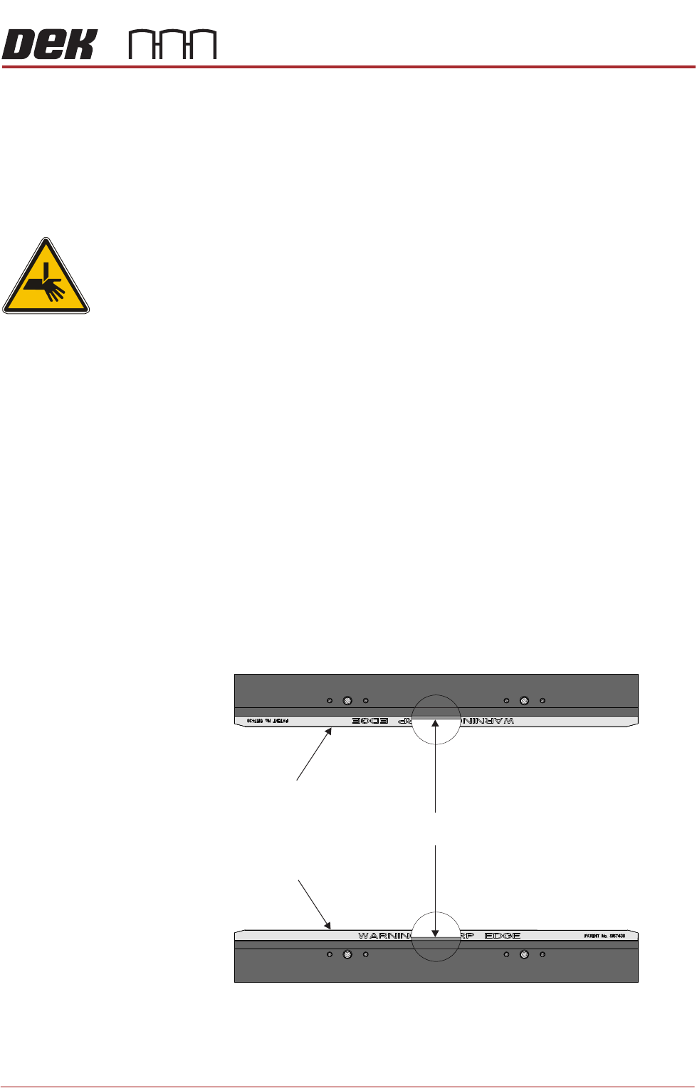
WARNING
BOARD CLAMPS. EXTREME CARE MUST BE EXERCISED WHEN WORKING IN
THE TOOLING AREA OF THE MACHINE TO AVOID INJURY. THE FOILS ON THE
FRONT AND REAR BOARD CLAMPS ARE VERY SHARP.
1. Ensure the board clamps are fitted and the Board Clamp Setting procedure
has been carried out.
2. In Diagnostics select Rapid Transit Conveyor module.
3. Select Home Rapid Transit Conveyor Inroad Vane Motor.
4. Select Home Rapid Transit Conveyor Board Transport Motor.
5. Select Home Rail Width.
6. Select Adjust and set board width to 250mm.
7. Select Exit.
8. Select Drive Rail to Board Width.
9. Select Run Diagnost.
10. Open the front printhead cover/shutter.
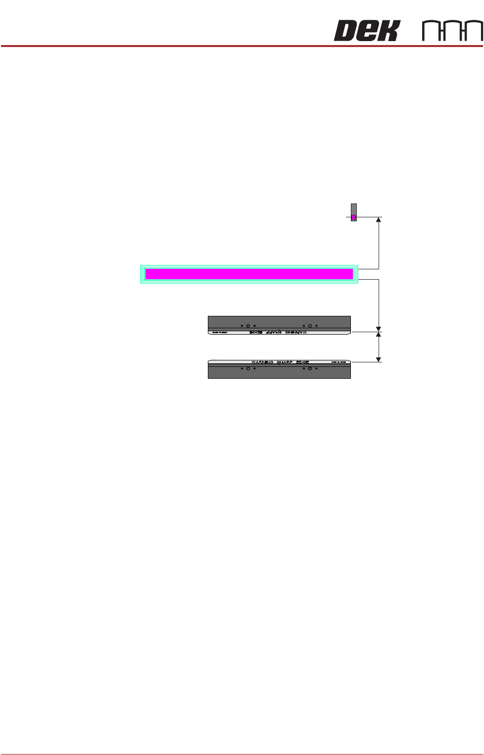
11. Place a vernier gauge just below the board clamp foil in the centre of the
board clamps and check that the vernier reads between 250.25mm
±0.10mm.
12. If the rail width is correct, go to Step 22.
13. Close the front printhead cover/shutter and press the System button when
Rear Board Clamp
Plan View of Board Clamps
250.25mm ±0.10mm
Front Board Clamp
RAPID TRANSIT CONVEYOR (RTC) MODULE
ADJUSTMENTS AND SETTINGS
22.18 Technical Reference Manual Chapter Issue 4, Aug 14
prompted.
14. Select Set Rail Board Width Calibration.
15. Select Run Diagnost to open the Rail Width Offset window.
16. Use Incr. or Decr. to set the offset required to achieve the dimension in Step
11.
NOTE
Increasing the offset increases the dimension between the rear rail and the
home position therefore, decreasing the width between the front and rear
rails.
17. Select Move.
18. Open the front printhead cover/shutter and recheck the measurement.
19. If the rail width is incorrect, close the front printhead cover/shutter, press the
System button and repeat Steps 16 to 18.
20. If the rail width is correct, close the front printhead cover/shutter, press the
System button and select Set.
21. Select Yes to save the information.
Inroad/Outroad Conveyors
Conveyor Height
Setting
The inroad and outroad conveyors must be the same height as the print station
for smooth transition of the board through the length of the rail system. Use the
following procedure to check and adjust the height:
1. To move the vanes clear of the front print station rails, set the board length
to maximum and home the rapid transit conveyor board loader.
2. Place the Board Clamp Setting Plate (140403) half on the print station and
half on the inroad conveyor.
3. Viewing from the left side of the machine, ensure that the board clamp
setting plate is in contact with the transport belts on the front and rear inroad
conveyors.
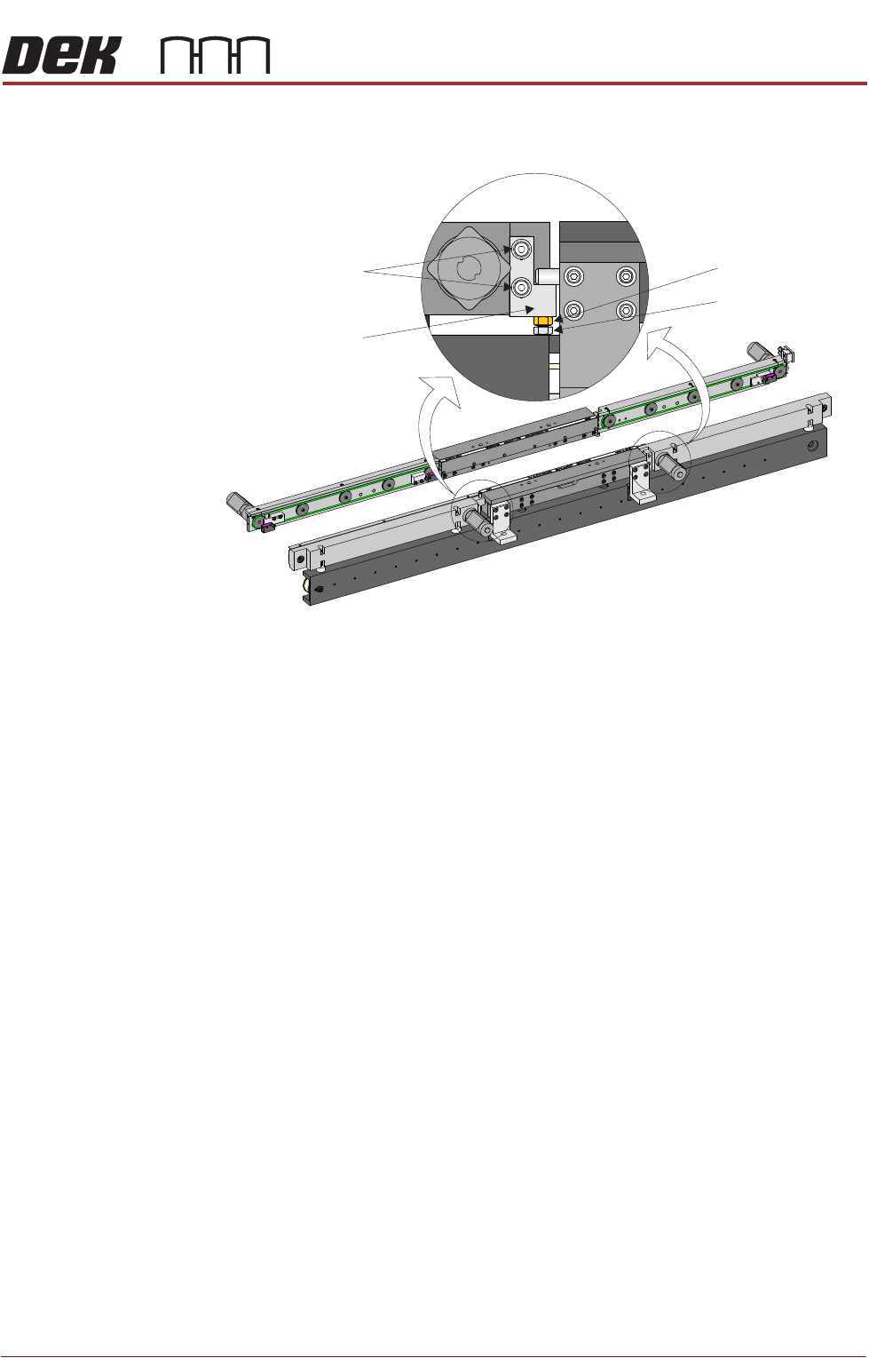
Plan View on Print Station of RTC Rails
Home Position
Rail Width
RAIL WIDTH OFFSET 0.00 mm
+/- 3.00mm
RAPID TRANSIT CONVEYOR (RTC) MODULE
ADJUSTMENTS AND SETTINGS
Chapter Issue 4, Aug 14 Technical Reference Manual 22.19
4. If adjustment is required on the front inroad conveyor, loosen the two print
station lift bracket locking screws on the front inroad conveyor.
5. Using an 8mm spanner, loosen the locking nut.
6. Adjust the adjusting screw until the board clamp setting plate is sitting evenly
on the print station board support plate and the transport belts of the front
inroad conveyor.
7. Tighten the two print station lift bracket locking screws on the front inroad
conveyor.
8. Using two 10mm spanners, hold the adjusting screw whilst tightening the
locking nut.
9. Recheck the level.
10. If adjustment is required on the rear inroad conveyor, move the board clamp
setting plate fully on to the inroad conveyor.
11. Manually lift the rear print station rail.
View on Front of RTC Rail System
Locking Screws
Print Station Lift
Bracket
Locking Nut
Adjusting screw