192277 - Micron Technical Reference Volume 3.pdf - 第149页
RISING TABLE MODULE - STYLE 2 CALIBRATIONS Chapter Issue 3, Feb 18 Technical Reference Manual 28.7 CALIBRA TIONS Print Height Print reference height is the height to which the rising ta ble is taken to achieve board clam…
RISING TABLE MODULE - STYLE 2
REPLACEMENT PROCEDURES
28.6 Techncial Reference Manual Chapter Issue 3, Feb 18
REPLACEMENT PROCEDURES
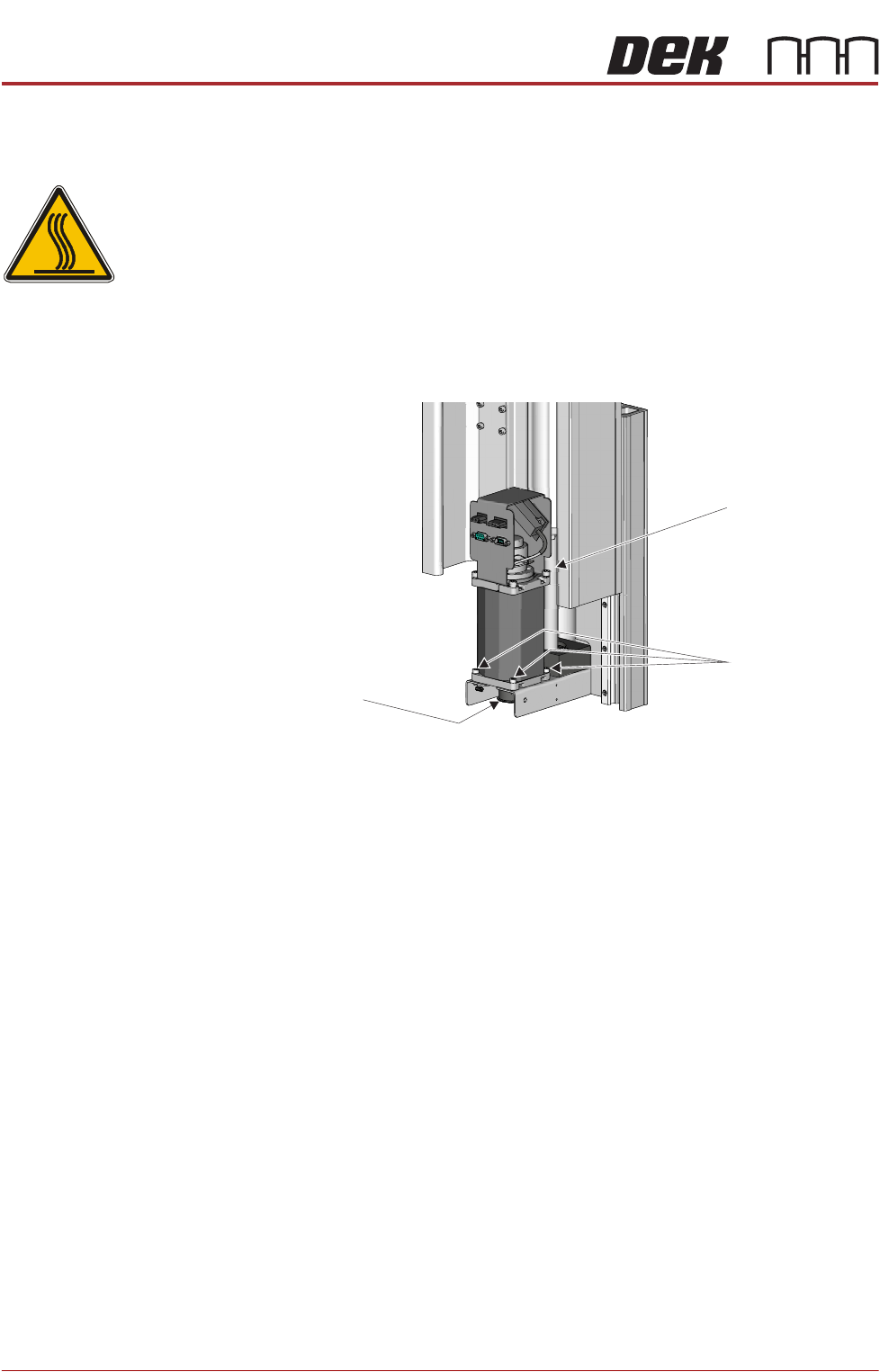
Rising Table Drive Belt
WARNING
HOT SURFACES. THE SURFACE OF THIS COMPONENT OR SURROUNDING
AREA MAY BECOME HOT DURING PROLONGED OPERATION. CARE TO BE
TAKEN WHEN WORKING IN THE VICINITY OF THIS COMPONENT.
1. Power down the printer and fit a lock to the mains isolator lock out.
2. Gain access to the rising table motor.
3. Using a 4mm Allen key, undo the three rising table motor securing screws.
4. Slide the rising table motor towards the leadscrew to slacken the drive belt.
5. Remove the drive belt and discard.
6. Fit the replacement drive belt.
7. Slide the rising table motor away from the leadscrew to tighten the drive belt
and ensure the motor is located correctly in the bracket cut out.
8. Whilst maintaining this tension, fasten and tighten the three rising table
motor securing screws.
9. Turn the mains power ON.
10. Carry out Rising Table Home Setting, Adjustments and Settings section of
this chapter refers.
Leadscrew
Rising Table
Motor Securing
Screws
View From Rear of Rising Table Motor Assembly
Rising Table
Drive Belt
RISING TABLE MODULE - STYLE 2
CALIBRATIONS
Chapter Issue 3, Feb 18 Technical Reference Manual 28.7
CALIBRATIONS
Print Height Print reference height is the height to which the rising table is taken to achieve
board clamp to stencil contact at zero board thickness. Print height is the height
the rising table is taken to print the product and is calculated as the print
reference height minus the board thickness and print gap. This calibration
accurately sets the board to stencil ‘set contact height’ and ensures constant
print pressure is applied. Deterioration in this calibration may result in inconsist-
ent print pressure thereby effecting the print quality.
1. Ensure that a stencil is fitted in the machine.
2. Select Maintenance.
3. Select Diagnostics.
4. Use Next or Previous to highlight Rising Table.
5. Select Select Module.
6. Ensure that Home Rising Table is highlighted.
7. Select Run Diagnost.
8. Use Next or Previous to highlight Set Reference Print Height.
9. Select Run Diagnost.
The rising table moves to the default setting and the following window is
displayed:
10. Select Confirm to open the Table Print Height Calibration window:
11. Check the gap between the top of the board clamps and the stencil. The
correct print height is when the top of the transport rails is just touching the
stencil.
12. Use the Incr. or Decr. button to adjust the displayed dimension.
13. Select Move.
14. Repeat Steps 11 to 13 until the top of the board clamps are in contact with
the stencil, without force.
15. When the correct height has been achieved, select Set Height.
Please confirm the following:
There is a screen loaded.
There is NO board loaded.
The aim of this calibration is to set the elevation of
the rising table to the point where the closed board
clamps are just in contact with the stencil.
While foil-less clamps or snuggers are being used,
ensure they have been adjusted to bring their top
surface level with the top surface of the board.
Upon completion of this calibration, the Squeegee
Reference Height should also be calibrated.
Set Reference Print Height
PRINT HEIGHT
Table Print Height Calibration
127.00
mm
RISING TABLE MODULE - STYLE 2
CALIBRATIONS
28.8 Techncial Reference Manual Chapter Issue 3, Feb 18
The following window is displayed:
16. Select Confirm to save the new print height.
17. Select Cancel to close the Set Reference Vision Height window.
18. Select Exit.
19. Select Exit.
20. Select Back.
21. Carry out the Squeegee Reference Height calibration, Squeegee chapter
refers.
Please confirm the following:
The board clamps are not lifting the stencil.
When the part of the stencil that is over the board
clamps is pressed, there is no perceptible movement.
To adjust the elevation of the board clamps, press
Cancel. Use Incr. And Decr. to alter the value of print
height. Use Move to apply the current value of print
height.
Set Reference Vision Height