192277 - Micron Technical Reference Volume 3.pdf - 第34页
RAPID TRANSIT CONVEYOR (RTC) MODULE ADJUSTMENTS AND SETTINGS 22.22 Technical Reference Manual Chapter Issue 4, Aug 14 Rear Conveyor Alignment The rear inroad and outroad conveyors taper slightly away from the print stati…
RAPID TRANSIT CONVEYOR (RTC) MODULE
ADJUSTMENTS AND SETTINGS
Chapter Issue 4, Aug 14 Technical Reference Manual 22.21
Front Conveyor
Alignment
The front inroad conveyor must be perfectly aligned to the print station rail as
the vanes travel the whole length of the rail system. Use the following procedure
to check and adjust the alignment:
1. To move the vanes clear of the front print station rails, set the board length
to maximum and home the rapid transit conveyor board loader.
2. Using a 1 metre straight edge rule above the transport belt on the inroad
conveyor and above the board support plate on the print station rail, check
that the inroad conveyor and print station are aligned.
3. If adjustment is required, loosen the two front inroad conveyor securing
screws.
4. Place a 5mm Allen key between the conveyor and the print station to
maintain the correct gap.
5. Adjust the conveyor to achieve alignment with the print station rail.
6. Tighten the securing screws, remove the Allen key and recheck the align-
ment.
7. Move the rapid transit conveyor board loader to the ready position.
8. Using a 1 metre straight edge rule above the transport belt on the outroad
conveyor and above the board support plate on the print station rail, check
that the outroad conveyor and print station are aligned.
9. If adjustment is required, loosen the two front outroad conveyor securing
screws.
10. Place a 5mm Allen key between the conveyor and the print station to
maintain the correct gap.
11. Adjust the conveyor to achieve alignment with the print station rail.
12. Tighten the securing screws, remove the Allen key and recheck the align-
ment.
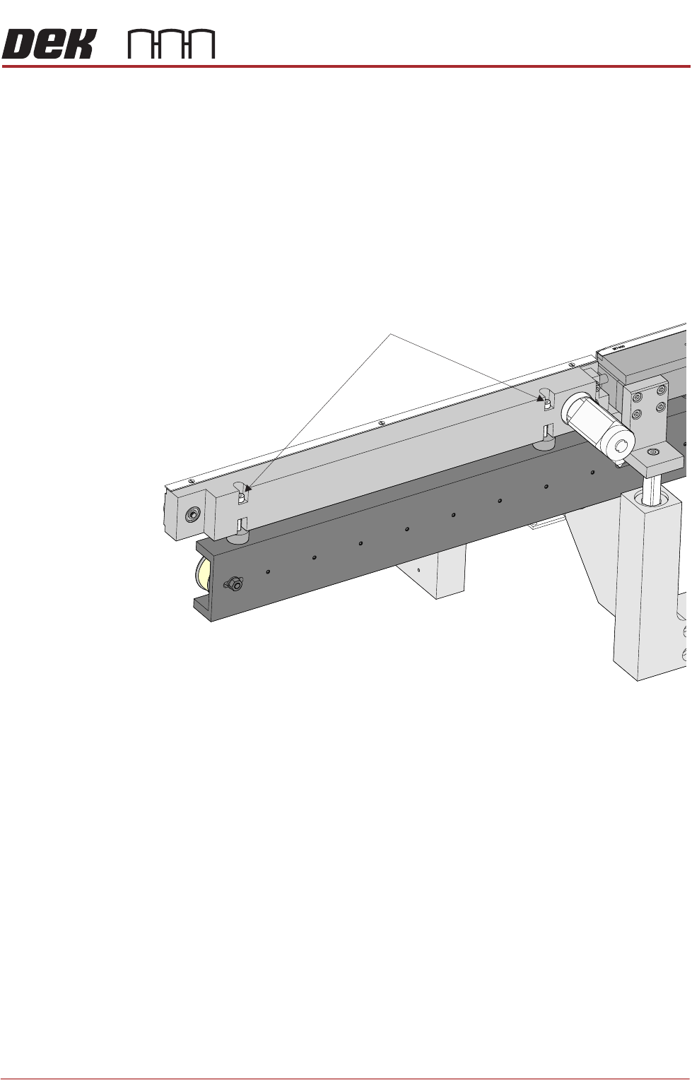
View on Front Inroad Conveyor
Front Inroad Conveyor Securing Screws
RAPID TRANSIT CONVEYOR (RTC) MODULE
ADJUSTMENTS AND SETTINGS
22.22 Technical Reference Manual Chapter Issue 4, Aug 14
Rear Conveyor
Alignment
The rear inroad and outroad conveyors taper slightly away from the print station.
Use the following procedure to check and adjust the alignment:
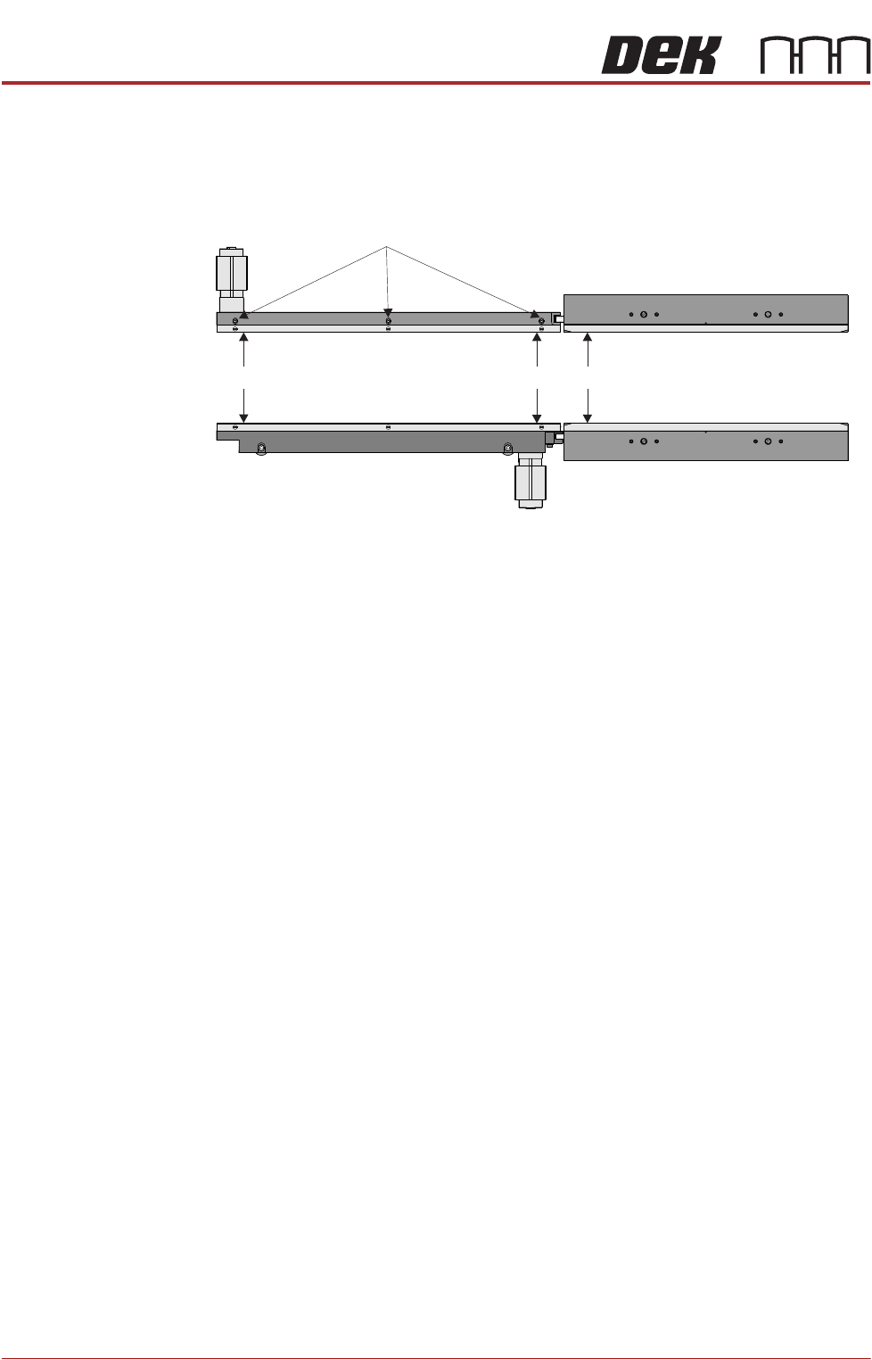
1. Using a vernier above the board support plate, measure the rail width on the
print station (Dimension A).
2. Measure the rail width on the inroad conveyor close to the print station
(Dimension B). Dimension B must be between Dimension A and A plus
0.05mm.
NOTE
Ensure that the measurement is taken from the flat and not the chamfered
end.
3. Measure the rail width on the inroad conveyor close to the end of the inroad
conveyor (Dimension C). Dimension C must be between Dimension B plus
0.10mm and B plus 0.20mm.
NOTE
Ensure that the measurement is taken from the flat and not the chamfered
end.
4. If adjustment is required, loosen the board guide securing screws and adjust
the board guide to achieve the measurements above.
5. Tighten the board guide securing screws.
6. Repeat Steps 1 to 5 for the outroad conveyor.
Rail Lifted Sensor There is no adjustment on the rail lifted sensor or the vane.
Board Guide Securing Screws
C
B
A
RAPID TRANSIT CONVEYOR (RTC) MODULE
ADJUSTMENTS AND SETTINGS
Chapter Issue 4, Aug 14 Technical Reference Manual 22.23
Board Ultra-sonic
Sensors
There are three board sensors:
• Board at Left Sensor
• Board at Stop Sensor
• Board at Right Sensor
Positional
Adjustment
The board sensors are adjustable in the X and Y directions to compensate for
any holes or cut-outs on the product board that coincide with the sensor when
the board is in the stopped position.
With the board in the stopped position over the sensor, if the sensor is not
seeing the board due to a hole or cut-out, use the following procedure to adjust
the sensor:
1. Power down the machine.
2. In the X direction; using a 2.5mm Allen key, loosen the two bolts that secure
the sensor to the bracket.
3. Move the sensor to the required position.
4. Tighten the two bolts that secure the sensor to the bracket.
5. In the Y direction; using a 2.5mm Allen key, loosen the two bolts that secure
the sensor bracket to the rails.
6. Move the sensor to the required position.
7. Tighten the two bolts that secure the sensor bracket to the rails.
8. Power up the machine and check for correct operation of the sensor.
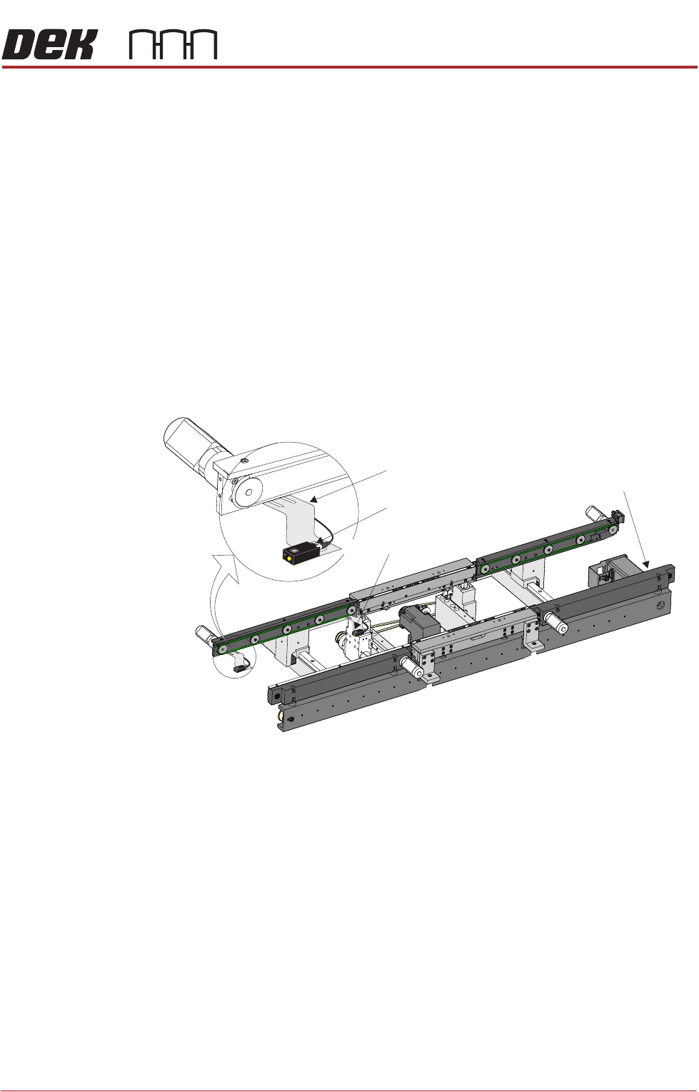
View on Front of RTC System
Board at Right Sensor
Board at Left Sensor
Sensor Bracket
Board at Stop Sensor