192277 - Micron Technical Reference Volume 3.pdf - 第82页
BLUE UNDER SCREEN CLEANER MODULE OVERVIEW 24.2 Technical Reference Manual C hapter Issue 1 0, Jul 16 The blue under screen cleaner (USC) wi pes lint free paper , dry or wet across the underside of the ste ncil to minimiz…
BLUE UNDER SCREEN CLEANER MODULE
OVERVIEW
Chapter Issue 10, Jul 16 Technical Reference Manual 24.1
CHAPTER 24 BLUE UNDER SCREEN CLEANER MODULE
OVERVIEW
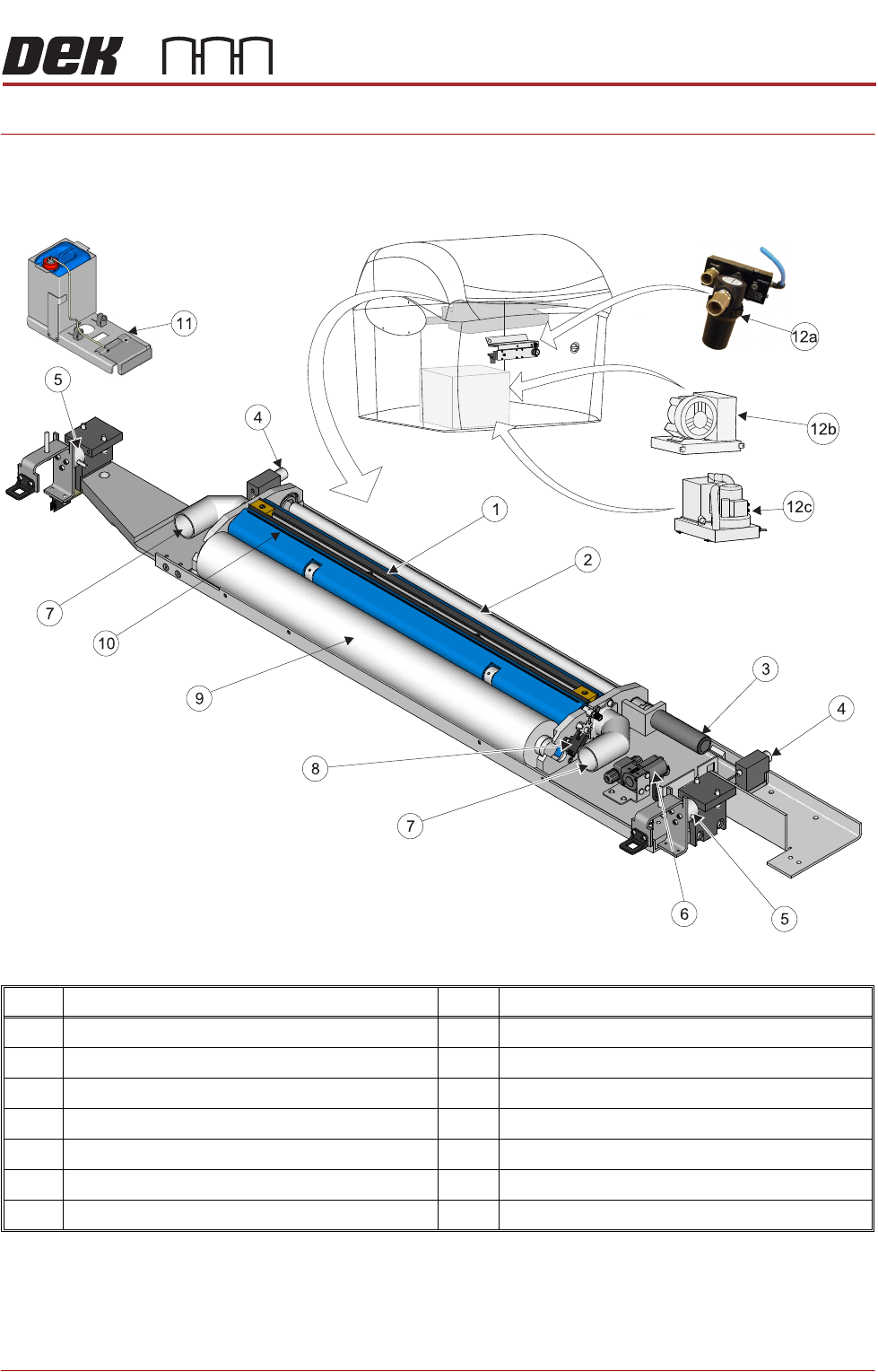
Figure 24-1 Blue Under Screen Cleaner
NOTE
Vacuum Filtration Units VF35i is located at the rear of Type 4 machines and
accessed by removing the rear panel.
Item Description Item Description
1 Squeegee Assembly 8 Paper Usage Sensor
2 Take Up Roll 9 Clean Paper Roll
3 Paper Feed Motor 10 Solvent Spray Bar
4 Permanent Magnet (2 positions) 11 External Solvent Tank
5 Electromagnetic Clamp (2 positions) 12a VF10 Venturi Vacuum Filtration Unit
6 Solvent Pump 12b VF35i Vacuum Filtration Unit
7 Vacuum Connector (2 positions) 12c VF25 Vacuum Filtration Unit
BLUE UNDER SCREEN CLEANER MODULE
OVERVIEW
24.2 Technical Reference Manual Chapter Issue 10, Jul 16
The blue under screen cleaner (USC) wipes lint free paper, dry or wet across
the underside of the stencil to minimize paste build up. The frequency and mode
(wet/dry/vac) is programmable in the product file.
When a stencil cleaner operation is required, the camera carriage approaches
the cleaner and attaches to the cleaner using two permanent magnets. The two
electromagnetic clamps holding the stencil cleaner unit in the home position are
de-energized allowing the camera carriage to control the cleaner. The paper
feed motor supplies a clean section of paper across the two rubber wiper blades
of the squeegee assembly. During a ‘Wet’ clean, a solvent pump dispenses
solvent through the solvent spray bar, wetting the width of the paper just behind
the squeegee assembly. The squeegee assembly is lifted (engaging the cleaner
with the underside of the stencil) and the camera carriage pulls the cleaner
across the underside of the stencil, removing any surplus print medium.
The two wiper blades form the mouth of the vacuum cleaner.
A paper usage sensor enables the software to monitor the paper roll usage. If
‘Time To Go’ is enabled, software measures how much paper is remaining and
displays this as a percentage. If ‘Time To Go’ is disabled, software monitors
the pulses from the sensor and if no pulses are detected during paper advance,
it is assumed that the paper roll is empty and displays an error message.
Solvent The solvent pump supplies solvent to the paper roll from the external solvent
tank, mounted on the rear or either side of the machine. The external solvent
tank container is capable of accommodating a 5 litre container of solvent. A load
cell in the base of the external solvent tank enables the software to calculate
the percentage level of solvent within the container.
Solvent Advice The plastic tubing that transports the solvent from the solvent tank to the
underscreen cleaner head is designed to withstand most types of solvent.
However, mixing of two different solvents can cause a chemical reaction and
seriously damage the plastic tubing. When changing to a different type of
solvent, the tubing must be replaced completely to prevent solvent leaks. To
obtain new tubing and replacement instructions, order Machine Performance
Upgrade (MPU) 601187*2.
ASM only recommend the DEK-PRO and the DEK-PRO XF (Environmentally
Friendly) USC solutions to be used with the under screen cleaner. The following
are available from ASM:
NOTE
The following solvents MUST NOT be used in the under screen cleaner unit,
however, this list is not complete and does not mean that any solvent not
mentioned is compatible, with DEK machines.
• Rosstech 106 FE
• Rosstech 162 ND
• Acetone
• Iso-Propyl Alcohol (IPA)
Description 1 Litre 5 Litre 20 Litre
DEK-PRO 173483 173485 431093
DEK-PRO XF 431513 431514 -
BLUE UNDER SCREEN CLEANER MODULE
OVERVIEW
Chapter Issue 10, Jul 16 Technical Reference Manual 24.3
Vacuum Filtration The vacuum filtration unit extracts solvent fumes and draws excess print
material onto the paper.
Vacuum filtration is optional and may be one of the following types:
• VF35i Vacuum Filtration Unit
• VF25 Vacuum Filtration Unit
• VF10 Venturi Vacuum Filtration Unit
NOTE
For information on the removal and replacement of the filters, refer to the
Preventive Maintenance manual.
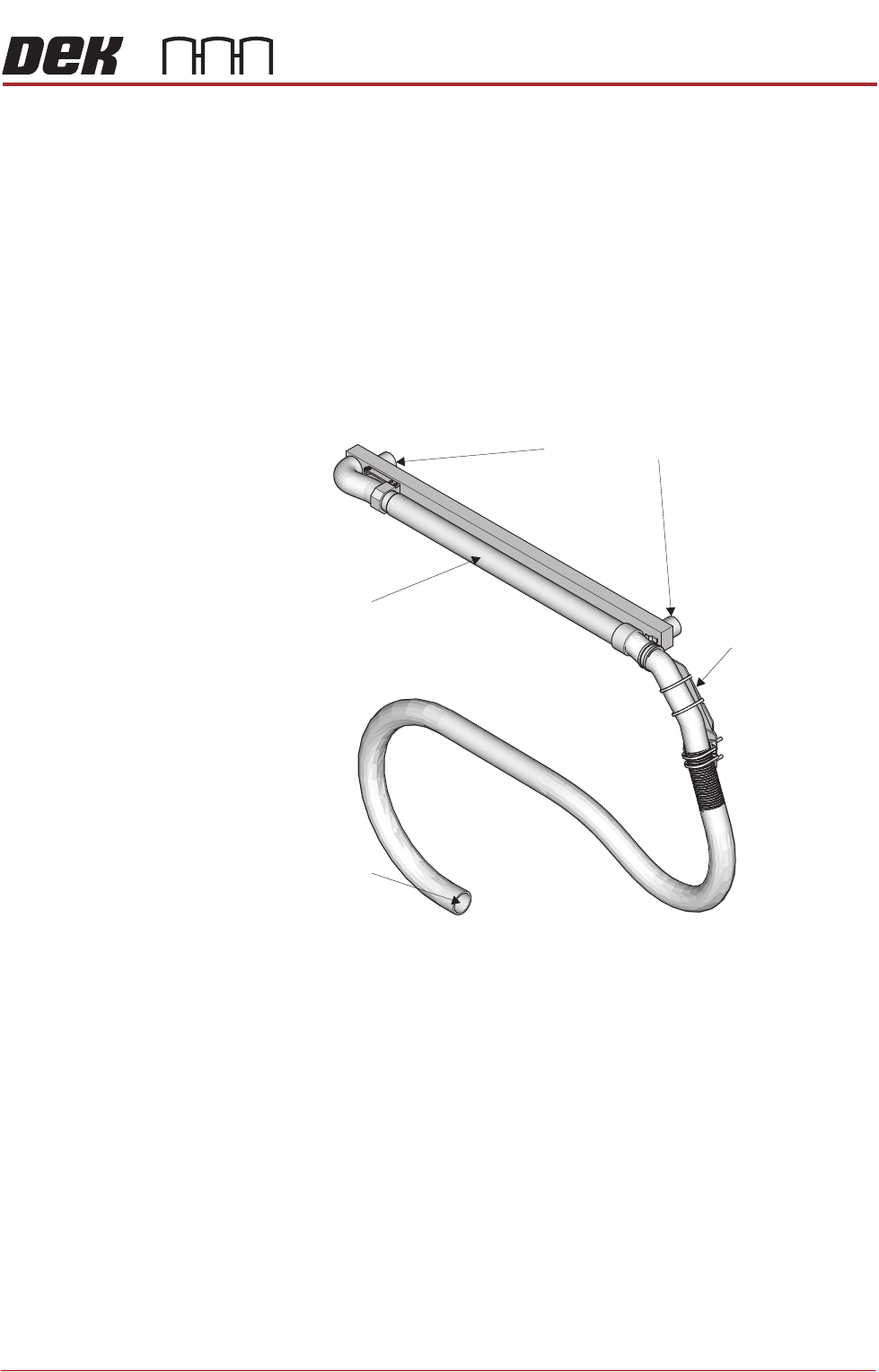
Figure 24-2 Vacuum Option
VF35i Vacuum
Filtration Unit
The onboard VF35i vacuum filtration unit is protected by two circuit breakers on
the front panel of the base unit. A 15A (for 115V) and an 8A (for 230V) which
can be reset by pressing the circuit breaker button covered by a clear plastic
protector. For safety, the voltage selector control knob is removed from the
switch and bolted to the fan housing. The VF35i vacuum filtration unit has a
three position mechanical air flow adjuster to regulate the air flow as follows:
• Maximum (full air flow)
• Medium (half air flow approximately)
• Minimum (15% of full air flow approximately)
VF25 Vacuum
Filtration Unit
The onboard VF25 vacuum filtration unit is protected by either a 10A (for 115V
units) or 5A (for 230V units) circuit breaker.
Screen Cleaner Connection
Vacuum Connection
Telescopic Tube
Machine Mount