192277 - Micron Technical Reference Volume 3.pdf - 第144页
RISING TABLE MODULE - STYLE 2 OVERVIEW 28.2 Techncial Reference Manual Chapter Issue 3, Feb 18 The rising table moves up and down within the machine supporting the product board, via the tooling, and accurately positions…
RISING TABLE MODULE - STYLE 2
OVERVIEW
Chapter Issue 3, Feb 18 Technical Reference Manual 28.1
CHAPTER 28 RISING TABLE MODULE - STYLE 2
OVERVIEW
NOTE
For details on the Remote Board Stop and sensors refer to the Board Stop
Chapter.
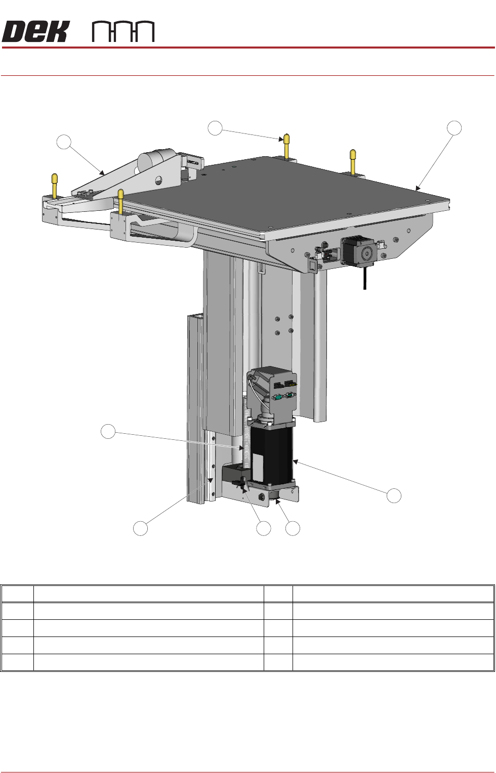
Item Description Item Description
1 Manual Tooling Plate 5 Linear Bearing Guide (in 2 positions)
2 Rising Table Motor with Integral Electromagnetic Brake 6 Rising Table Leadscrew
3 Rising Table drive belt 7 Remote Board Stop (Optional) See Note.
4 Home Sensor 8 Rail to Table Height Adjuster (in 4 positions)
View on Rear of Rising TableLeft
5
2
7
1
4 3
6
8

RISING TABLE MODULE - STYLE 2
OVERVIEW
28.2 Techncial Reference Manual Chapter Issue 3, Feb 18
The rising table moves up and down within the machine supporting the product
board, via the tooling, and accurately positions the height of the rails at several
different pre-determined heights during the print cycle. The rising table contains
the attachment points for the transport rails and the drive for the moving rear
rail, for more information refer to the Transport Rails chapter.
The rising table heights, determined by the software and referenced from the
home position, are as follows:
• Home Position
• Transport Height
• Vision Height
• Print Height
The rising table homes only when the machine initialises, this is achieved at
power up or when exiting diagnostics. Transport height is preset in the product
file allowing clearance for the board to clear the tooling whilst entering and
leaving the machine. Vision height brings the board into the camera focal length
for the vision system. The board is paused at this height whilst stencil alignment
is achieved. The rising table is taken up to print height for the board to be
printed.
The rising table also supports the remote board stop which is used for position-
ing large or heavy boards.
RISING TABLE MODULE - STYLE 2
ELECTRICAL SCHEMATIC
Chapter Issue 3, Feb 18 Technical Reference Manual 28.3
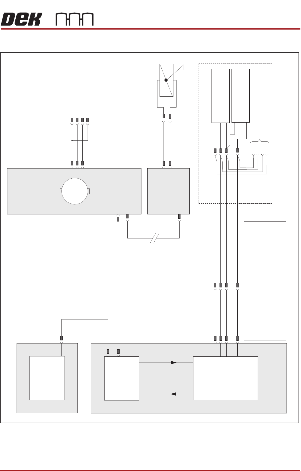
ELECTRICAL SCHEMATIC
NextMove ES
(I/O Node 1)
X5
Machine Control Enclosure
NextMove
Interface Card
X4
I/Ps O/Ps
Remote Board Stop (optional)
If Remote Board Stop is
Right Hand Side Configured
Board Stop Extended
Sensor (10SE25)
Board At Stop
Sensor (10SE26)
8SK05(L)
8SK05(R)
+12V
0V
0V
Sig
Sig
USB
M36PL11
BPL6A
BSK6
M36PL28
3PL35
Motherboard
Machine PC
NOTES
The breaks in the CAN Bus chain reflect that additional1.
I/O Nodes may be fitted, refer to Machine Control
chapter for the complete CAN Bus chain.
2. Camera Board Stop sensors are detailed in the Camera
chapter of this manual.
3. Rail Lift sensors are detailed in the respective Transport
Rails chapter of this manual.
Rising Table
Home Sensor
(8SE1)
N6 4PL
(8M1)
Rising Table Motor
Servo Node 6
CAN In
N6 3PL
M36PL35
CAN Bus
(see Note)
Main Machine
I/O Node 2
Board Stop
(16SOL14)
Manual Operation
16SK14
N2PL4
N2SK2
M
CAN Out
N6SK2
+24V
SIG
0V
(L)