192277 - Micron Technical Reference Volume 3.pdf - 第223页
FOREIGN MACHINE INTERFACE MULTI-INTERFACE UNIT Chapter Issue 5, Aug 14 Technical Reference Manual 33.21 Figure 33-19 SMEMA Logical Timing Diagram NOTES A board transfer occurs when a board is available (contact closed) a…
FOREIGN MACHINE INTERFACE
MULTI-INTERFACE UNIT
33.20 Technical Reference Manual Chapter Issue 5, Aug 14
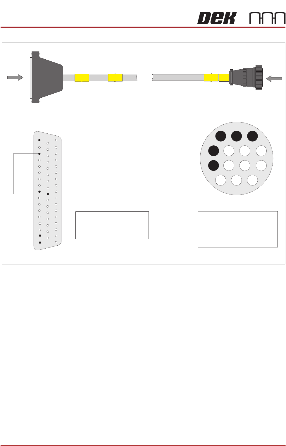
Figure 33-18 SMEMA Downline Interface Cable
B
PLB
SMEMA Downline Plug
AMP 206044-1
A
PLA
DEK Machine
50 Way D-type
View on Arrow B
1
3
2
8
4
Pin 1 - Machine Ready (H)
Pin 4 - Board Available (H)
Pin 8 - Shield
Pin 2 - Machine Ready (L)
Pin 3 - Board Available (L)
View on Arrow A
33
25
9
15
2
50
1
18
34
17
Pin 1 - Machine Ready (L)
Pin 9 - Board Available (H)
Pin 2 - Machine Ready (H)
Pin 17 - Board Available (L)
FOREIGN MACHINE INTERFACE
MULTI-INTERFACE UNIT
Chapter Issue 5, Aug 14 Technical Reference Manual 33.21
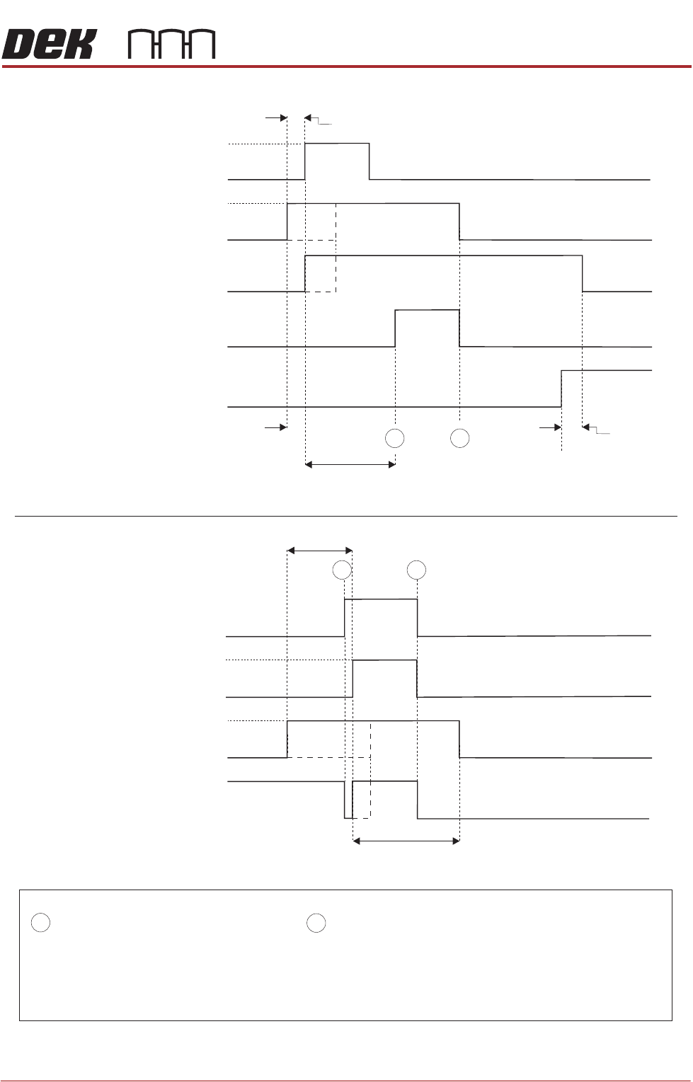
Figure 33-19 SMEMA Logical Timing Diagram
NOTES
A board transfer occurs when a board is available (contact closed) and the machine is ready (contact closed).
The Board Available signal and Machine Ready signal can occur at anytime, but board transfer does not occur
until both contacts are closed.
The Board Available signal remains closed until the board has left the machine.
The Machine Ready signal remains closed until the board has arrived at the next machine.
- Board Trailing Edge at Sensor
- Board Leading Edge at Sensor
A
B
Downline
Downline M/C
(I/P to DEK M/C)
Board Not Available
Board Available
DEK M/C Belts Running
DEK M/C Output Sensor
DEK M/C
(O/P from DEK M/c)
Machine Ready
Machine Not Ready
A
B
Upline
DEK M/C Input Sensor
Upline M/C
(I/P to DEK M/C)
Board Not Available
Board Available
DEK M/C
(O/P from DEK M/C)
Machine Ready
Machine Not Ready
DEK M/C Board At Stop Sensor
Board At Stop
Transfer Complete
< Transfer Period
< Transfer Period
< Transfer Period
< Transfer Period
Belt Overrun
DEK M/C Belts Running
A
B
DEK M/C Ready
FOREIGN MACHINE INTERFACE
MULTI-INTERFACE UNIT
33.22 Technical Reference Manual Chapter Issue 5, Aug 14
Siemens Interface
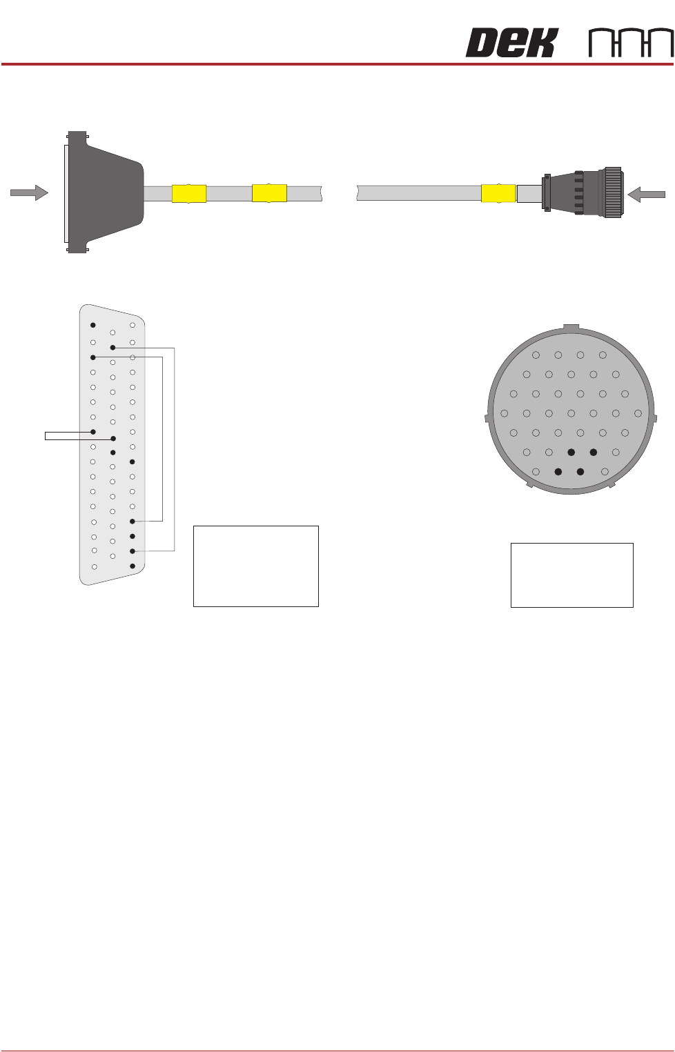
Figure 33-20 Siemens Upline Interface Cable
B
Siemens Downline Plug
AMP 206305-1
PLS1
A
7PL02
DEK Machine
50 Way D-type
View on Arrow B
1
5
10
16
23
29
34
35
31
36
4
9
15
22
28
33
32
37
Pin 31 - Arrived
Pin 32 - Permission
Pin 35 - Released
Pin 36 - Request
Pin 17 - 0V (Out)
Pin 25 - Relaeased
Pin 34 - Arrived
Pin 36 - Permission
Pin 41 - Request
View on Arrow A
33
26
25
41
10
15
2
50
1
18
34
35
36
37
17