192277 - Micron Technical Reference Volume 3.pdf - 第207页
FOREIGN MACHINE INTERFACE FMI POD Chapter Issue 5, Aug 14 Technical Reference Manual 33.5 Figure 33-4 SMEMA Upline Extension Cable Figure 33-5 SMEMA Downline Extension Cable View on Arrow B View on Arrow A 1 3 4 8 2 1 3 …
FOREIGN MACHINE INTERFACE
FMI POD
33.4 Technical Reference Manual Chapter Issue 5, Aug 14
SMEMA Interface
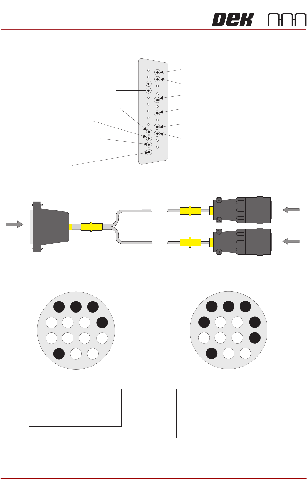
Figure 33-3 SMEMA Interface Cable
Pin 16 - Downline M/C Ready
Pin 24 - Board Fail (Downline)
Pin 17 - Downline M/C Ready 0V Return
Pin 25 - Board Fail (Downline) 0V Return
Pin 19 - Board Available (Downline)
Pin 21 - Board Available (Downline) 0V Return
Pin 2 - DEK M/C Ready 0V Return
Pin 4 - Board Available (Upline) 0V Return
0V
Pin 1 - DEK M/C Ready
Pin 3 - Board Available (Upline)
View on Arrow A
1
14
25
13
View on Arrow B
1
3
4
8
2
View on Arrow C
1
2
3
4
8
Pin 1 - DEK M/C Ready
Pin 2 - DEK M/C Ready 0V Return
Pin 3 - Board Available
Pin 4 - Board Available 0V Return
Pin 14 - Shield
Pin 1 - Downline M/C Ready
Pin 2 - Downline M/C Ready 0V Return
Pin 3 - Board Available
Pin 4 - Board Available 0V Return
Pin 7 - Board Fail
Pin 8 - Board Fail 0V Return
Pin 14 - Shield
B
C
SK A Upline
SK B Downline
A
M28PL02
DEK Machine
25 Way D-type
SMEMA Upline /Downline Sockets
AMP 206043-3
FOREIGN MACHINE INTERFACE
FMI POD
Chapter Issue 5, Aug 14 Technical Reference Manual 33.5
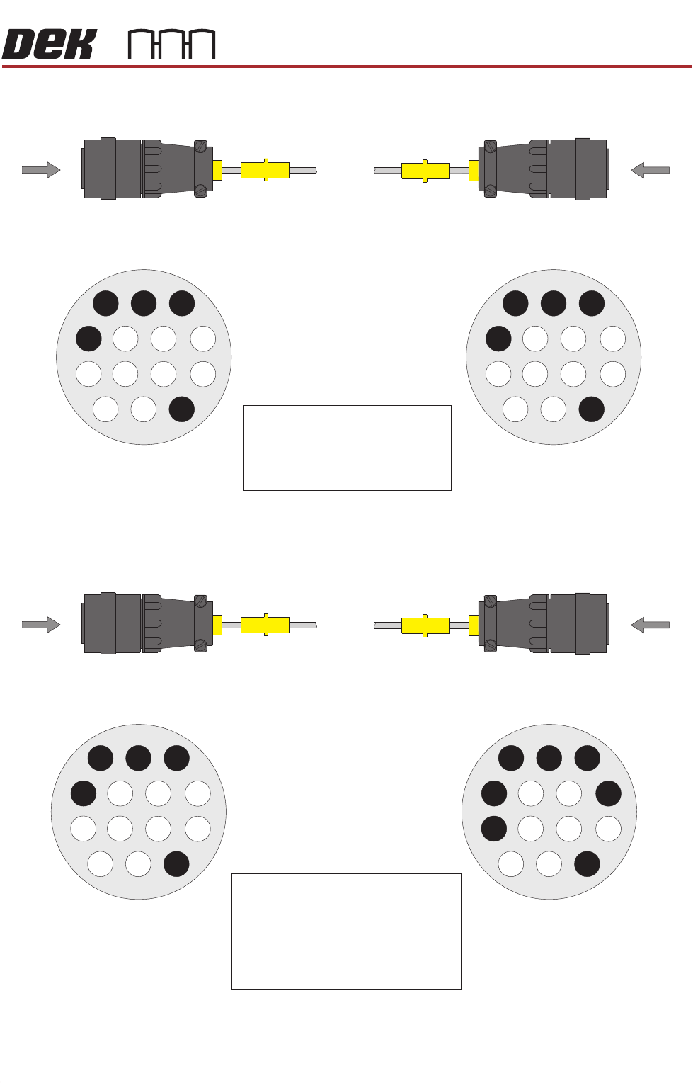
Figure 33-4 SMEMA Upline Extension Cable
Figure 33-5 SMEMA Downline Extension Cable
View on Arrow BView on Arrow A
1
3
4
8
2
1
3
4
8
2
Pin 1 - DEK M/C Ready
Pin 2 - DEK M/C Ready 0V Return
Pin 3 - Board Available
Pin 4 - Board Available 0V Return
Pin 14 - Shield
Up Plug
PL A
SMEMA Upline Plug
AMP 206044-1
SMEMA Upline Plug
AMP 206044-1
B
A
View on Arrow A View on Arrow B
1
3
4
8
2
1
3
4
8
2
Pin 1 - Downline M/C Ready
Pin 2 - Downline M/C Ready 0V Return
Pin 3 - Board Available
Pin 4 - Board Available 0V Return
Pin 7 - Board Fail
Pin 8 - Board Fail 0V Return
Pin 14 - Shield
Down Plug
PL B
SMEMA Downline Plug
AMP 206044-1
SMEMA Downline Plug
AMP 206044-1
B
A
FOREIGN MACHINE INTERFACE
FMI POD
33.6 Technical Reference Manual Chapter Issue 5, Aug 14
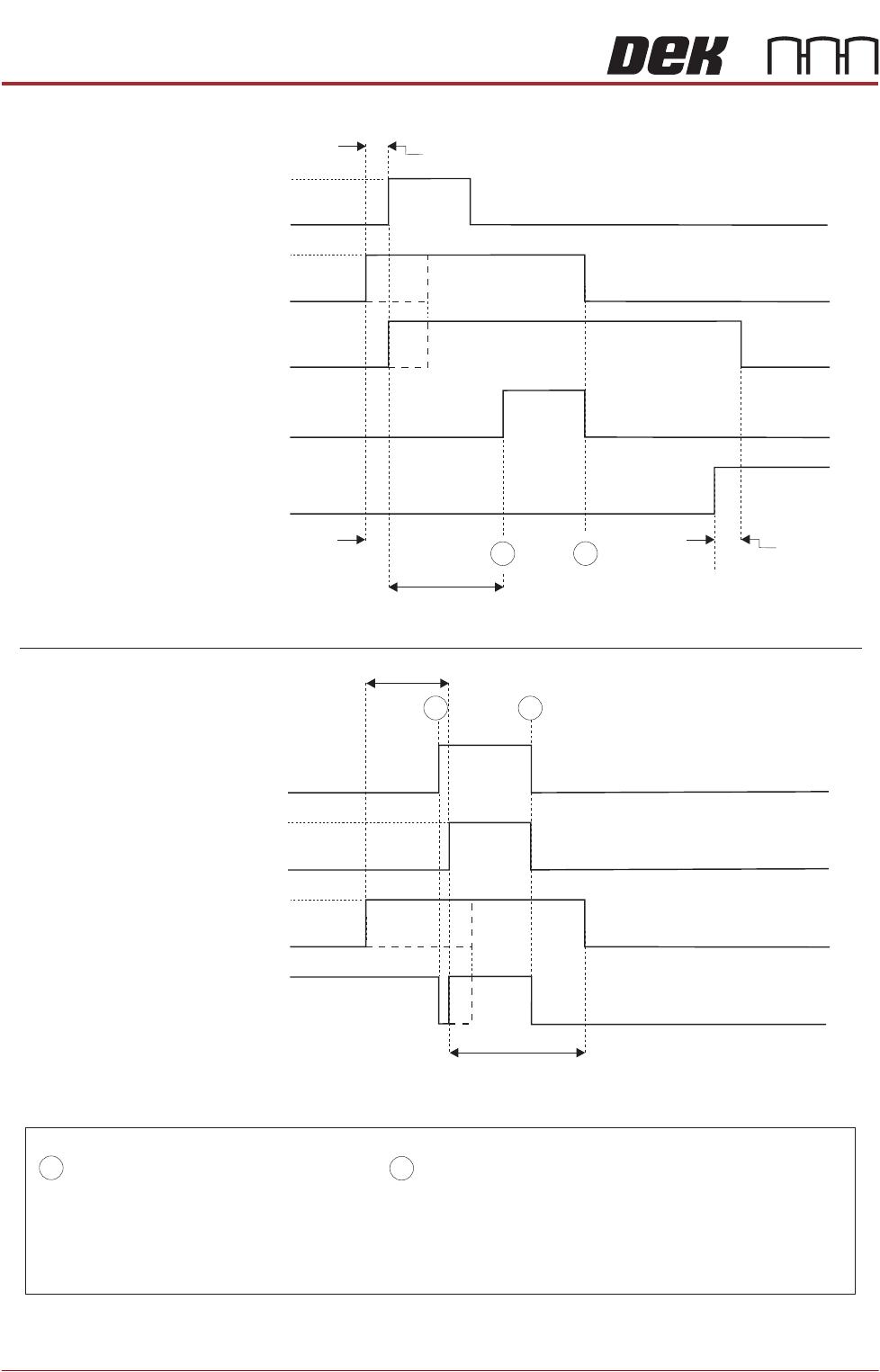
Figure 33-6 SMEMA Logical Timing Diagram
NOTES
A board transfer occurs when a board is available and the machine is ready.
The Board Available signal and Machine Ready signal can occur at anytime, but board transfer does not occur
until both signals are present.
The Board Available signal is present until the board has left the machine.
The Machine Ready signal is present until the board has arrived at the next machine.
- Board Trailing Edge at Sensor
- Board Leading Edge at Sensor
A
B
Downline
Downline M/C
(I/P to DEK M/C)
Board Not Available
Board Available
DEK M/C Belts Running
DEK M/C Output Sensor
DEK M/C
(O/P from DEK M/C)
Machine Ready
Machine Not Ready
A
B
Upline
DEK M/C Input Sensor
Upline M/C
(I/P to DEK M/C)
Board Not Available
Board Available
DEK M/C
(O/P from DEK M/C)
Machine Ready
Machine Not Ready
DEK M/C Board At Stop Sensor
Board At Stop
Transfer Complete
< Transfer Period
< Transfer Period
< Transfer Period
< Transfer Period
Belt Overrun
DEK M/C Belts Running
A
B
DEK M/C Ready