192277 - Micron Technical Reference Volume 3.pdf - 第22页
RAPID TRANSIT CONVEYOR (RTC) MODULE ELECTRICAL SCHEMATIC 22.10 Technical Reference Manual Chapter Issue 4, Aug 14 ELECTRICAL SCHEMA TIC Machine PC Motherboard Machine Control Enclosure DIG IN 10 DIG IN 1 1 DIG IN 6 Rail …

RAPID TRANSIT CONVEYOR (RTC) MODULE
OVERVIEW
Chapter Issue 4, Aug 14 Technical Reference Manual 22.9
RTC Rising Table The RTC system uses the standard rising table mechanism but incorporates a
smaller manual tooling plate and different home vane.
The manual tooling plate measures 295mm from left to right and the maximum
board length is 375mm. Therefore, any boards greater than 295mm in length
must be supported using dedicated or Grid-Lok tooling.
The tooling locating dowel holes on the rising table are located in a different
position to the standard rising table. For more information refer to the Vacuum
Box Tooling section of the Board Support Tooling Module.
The rising table home vane on the RTC machine ensures that the home position
is 10mm higher than a standard machine.
The rails on the RTC machine are 5mm lower than a standard machine
(measured from the stencil), that combined with the rising table home position
means that the maximum under board clearance is reduced by 15mm to 27mm
(25mm available in software to allow for adequate clearance).
NOTE
For tooling options see the board support tooling chapter.
Board
Tooling Manual Tooling Plate
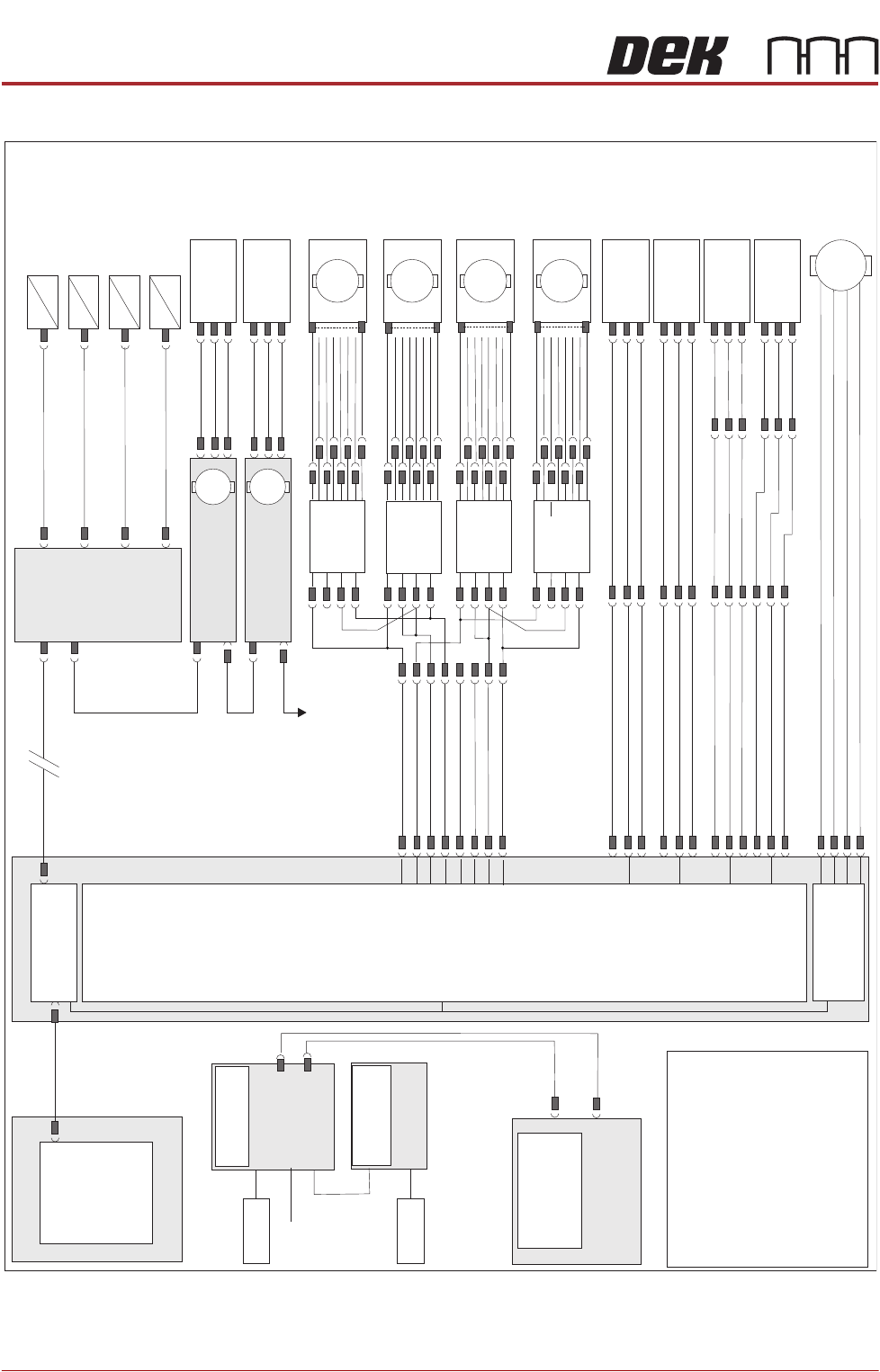
RAPID TRANSIT CONVEYOR (RTC) MODULE
ELECTRICAL SCHEMATIC
22.10 Technical Reference Manual Chapter Issue 4, Aug 14
ELECTRICAL SCHEMATIC
Machine PC
Motherboard
Machine Control Enclosure
DIG IN 10
DIG IN 11
DIG IN 6
Rail Lift
Sensor (8SE5)
Outroad Board
Sensor (8SE7)
Inroad Board
Sensor (8SE8)
8PL10
8PL04
M36PL17
8PL03
8PL12
Dual Stepper
X3
NextMove
Interface Card
X4
NextMove ES
(I/O Node 1)
X5
Main Machine
I/O Node 2
Board Clamp
Solenoid (16SOL10)
DIG OUT 9
Rail Width Clamp
Solenoid (16SOL14)
DIG OUT 10
Outroad Board Stop
Solenoid (16SOL22)
DIG OUT 12
Inroad Vane Lift
Solenoid (16SOL03)
DIG OUT 15
N2PL4
16SK14
CAN Bus
CAN Bus
M37PL20
M37PL09
N2SK2
N11SK3
N12SK3
N2SK3
N11PL4
* See Notes 2,3.
N12PL4
USB
3PL35
M36PL28
NOTES
The breaks in the CAN Bus chain1.
reflect that additional I/O Nodes may
be fitted, refer to Machine Control
chapter for the complete CAN Bus
chain.
2. I/O Node 11 becomes I/O Node
16 when the machine is configured
for Right to Left feed.
3. Motors 8M17 thru 8M21 are wired
opposite to the wiring shown when
the machine is configured for Right
to Left Feed
+
Sig
0V
DIG IN 8
Board At Stop
Sensor (8SE32)
M36PL11
8PL147
8PL148
+
Sig
0V
+
Sig
0V
+
Sig
0V
Transport
Mechanism
Home (8SE31)
N11PL01
+
Sig
0V
Moving Rail
Home (8SE6)
N12PL01
+
Sig
0V
M36PL22
Vane Stepper
Motor (8M19)
Motor 2B-
Motor 2A-
Motor 2B+
Motor 2A+
M
8PL22
M36PL18
+V
+V
+V
Dir
Dir
Enable
DIG OUT 2
DIG OUT 2
DIG OUT 3
DIG OUT 3
Enable
0V
0V
0V
Right R-L
Speed
Controller
BGE 3004
8SK135
Front Outroad
Belt Drive
(8M21)
M
Right L-R 8PL101
Speed
Controller
BGE 3004
8SK133
Rear Outroad
Belt Drive
(8M18)
M
Rear Inroad
Belt Drive
(8M17)
Left L-R
Speed
Controller
BGE 3004
8SK132
M
Front Inroad
Belt Drive
(8M20)
Left R-L 8SK95
Speed
Controller
BGE 3004
8SK134
M
* I/O Node 11
Transport Mechanism
Servo Motor
I/O Node 12
Rail Width
Stepper Motor
M
M
To I/O Node 4
PSU
RTC
Board Load
Rail Width Motor
Node 12
Board Load
Sensor
Rail Home
Sensor
CAN In
CAN Out
RAPID TRANSIT CONVEYOR (RTC) MODULE
ADJUSTMENTS AND SETTINGS
Chapter Issue 4, Aug 14 Technical Reference Manual 22.11
ADJUSTMENTS AND SETTINGS
Rising Table Home
Setting
To check and adjust the rising table home setting, refer to the Rising Table
Module of this manual.
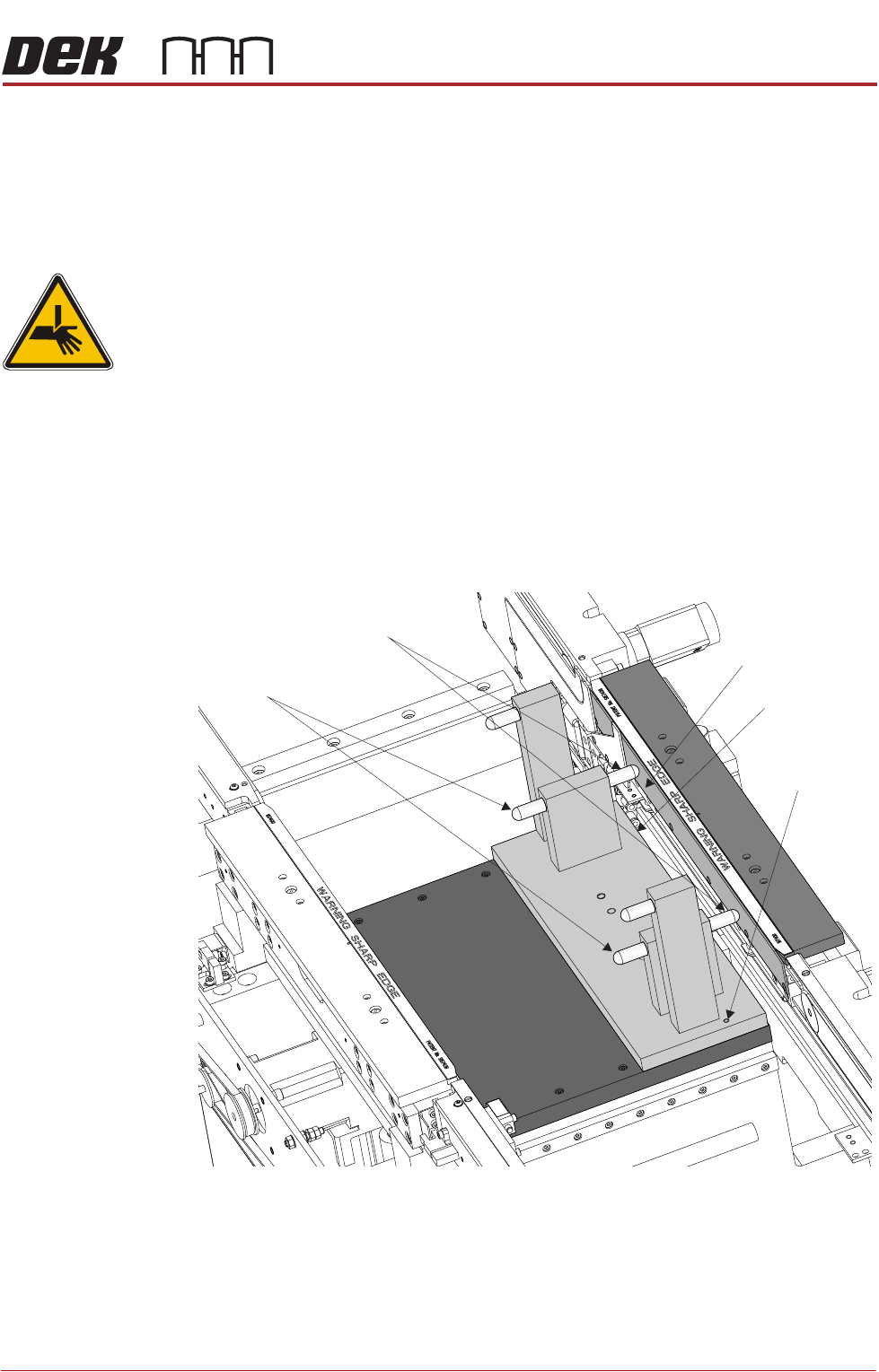
Parallelism
WARNING
BOARD CLAMPS. EXTREME CARE MUST BE EXERCISED WHEN WORKING IN
THE TOOLING AREA OF THE MACHINE TO AVOID INJURY. THE FOILS ON THE
FRONT AND REAR BOARD CLAMPS ARE VERY SHARP.
Parallelism of the print station rails and the camera X axis requires the Rail
Setting Jig (187652).
Front Rail
Parallelism
1. To move the vanes clear of the front print station rails, set the board length
to maximum and home the transport mechanism.
2. Home the RTC rails and set the rising table to vision height.
3. Fit the rail setting jig to the manual tooling plate locating the two dowels in
to the holes on the tooling plate.
NOTE
The rail setting jig must not exert any force on the front rail during placement.
If any force is felt, remove the jig, loosen the front print station rail securing
screws as described in Step 6, refit the jig and continue with Steps 7 to 9.
4. Using a 0.05mm feeler as a NO-GO gauge, check that the stops on the rail
setting jig abut the board support plate on the front print station rail.
Board Support Plate
Rail Setting Jig
Locating Dowel
(in 2 positions)
Rear Rail Stops
Front Rail Stops