192277 - Micron Technical Reference Volume 3.pdf - 第273页
PNEUMATIC MODULE ADJUSTMENTS AND SETTINGS Chapter Issue 7, Aug 14 Technical Reference Manual 35.7 ADJUSTMENTS AND SETTINGS Pressure Switch and Mains Air Regulator Setting 1. Set the mains air regulator (black pointer) to…
PNEUMATIC MODULE
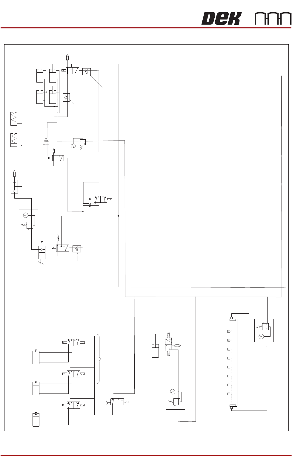
PNEUMATIC SCHEMATICS
35.6 Technical Reference Manual Chapter Issue 7, Aug 14
Figure 35-2 Pneumatic Schematic Sheet 2
HTC Aux Conveyor Board Stops
L-R=
L/H D’Line
Board Stop
L-R=
R/H UpLine
Board Stop
L-R=
R/H D’Line
Board Stop
Stinger Dispense
M27SOL02
M27SOL03
M27SOL01
R/H Conveyor
Solenoids
5/2
16SOL10
AB
Clamp
Speed
Control
Unclamp Delay Control
Fitted at Solenoid
Valve on Rear of M/C
Board Clamps
Snuggers Option
Snuggers
Out
Out
In
In
Pressure Control
Snuggers On
Stinger Option
Snugger
Delay
Control
Board Clamp
Reg (optional)
In
Out
Air Ionizer Option
Out
In
See Sheet 1
PNEUMATIC MODULE
ADJUSTMENTS AND SETTINGS
Chapter Issue 7, Aug 14 Technical Reference Manual 35.7
ADJUSTMENTS AND SETTINGS
Pressure Switch
and Mains Air
Regulator Setting
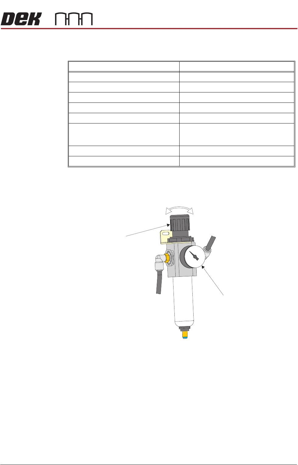
1. Set the mains air regulator (black pointer) to 0.3MPa (3 bar) by turning the
regulator control valve, clockwise to increase the pressure and anti-clock-
wise to decrease it.
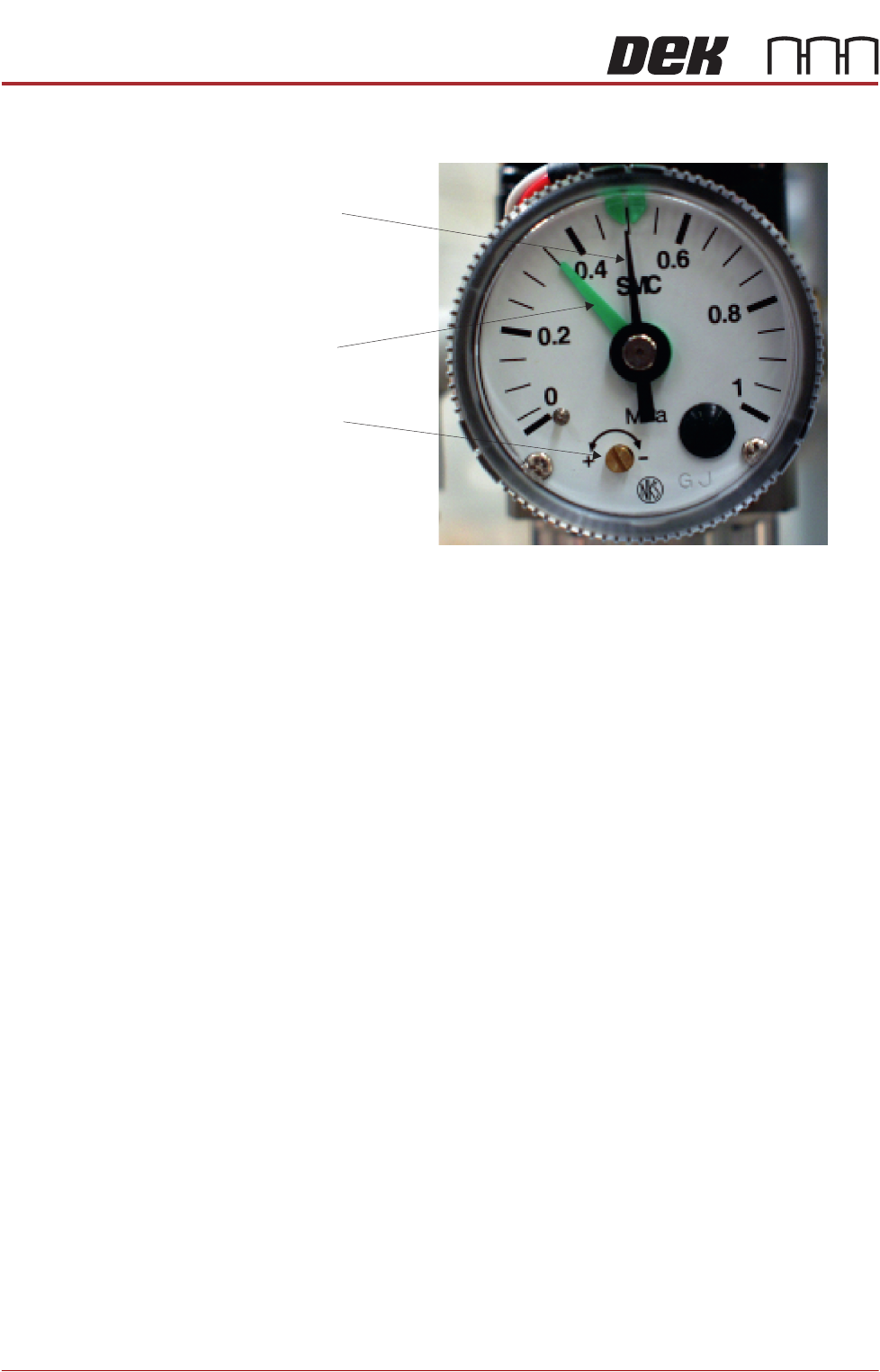
2. Turn the cover on the pressure sensor and gauge anti-clockwise and
remove.
3. Set the pressure sensor (green pointer) by using a screwdriver to turn the
brass set screw slowly until the tricoloured beacon changes from green to
red, clockwise to decrease the pressure and anti-clockwise to increase it.
When the tricoloured beacon just changes to red, the pressure sensor is
correctly set at 0.3MPa (3 bar).
4. Replace the cover on the pressure sensor and gauge and turn clockwise to
lock.
Regulator Setting
Mains Air Input 0.5MPa (5 bar)
Paste Dispenser 43 psi (3 bar) maximum
Snuggers 29 psi (2 bar) maximum
Chase Clamps see Chase Clamp Regulator Setting
Board Clamps 0.5MPa (5 bar) maximum
ProFlow - Software Regulator:
ProFlow Idle Paste
ProFlow Paste Pressure
0.2 bar
0.2 bar to 4 bar
ProFlow ATx (Paste Dispenser Regulator) 1.3 to 1.7 bar
Air Ionizer 0.175MPa (1.75 bar)
Regulator
Control
Valve
Pressure Sensor
and Gauge
PNEUMATIC MODULE
ADJUSTMENTS AND SETTINGS
35.8 Technical Reference Manual Chapter Issue 7, Aug 14
5. Reset the mains air regulator to 0.5MPa (5 bar).
Chase Clamp
Regulator Setting
The chase clamp regulator is located at the rear of the left hand print head,
overview diagram in the Screen Alignment Module refers.
There are two procedures for setting the chase clamp regulator depending on
whether a digital or spring balance type forcemeter is used. Select the appro-
priate procedure below:
Digital Forcemeter 1. Remove/open the rear printhead cover.
2. Open the front printhead cover.
3. Set the chase clamp regulator to 0.2MPa (2 bar) by turning the regulator
control valve, clockwise to increase the pressure and anti-clockwise to
decrease it.
4. From the rear of the printer, place the forcemeter up against the rear of the
chase.
5. Noting the reading, gradually push the forcemeter until the chase starts to
slip within the chase clamps. The reading should be between 12.2kg and
13.0kg.
6. Adjust the chase clamp regulator to achieve this value.
7. Refit/close the rear printhead cover.
Spring Balance
Forcemeter
1. Select Open Cover Commands.
2. Select Carriage To Rear.
3. Select Unload Screen.
4. Open the front printhead cover.
5. Remove the stencil from the printer.
6. Fit an empty stencil frame into the chase.
7. Attach a cable tie to the front of the empty stencil frame.
8. Close the front printhead cover.
9. Press the System button.
Pressure Sensor
Brass Set Screw
Pressure Sensor
Green Pointer
Mains Air Regulator
Black Pointer