192277 - Micron Technical Reference Volume 3.pdf - 第179页
PASTE ROLL HEIGHT MONITOR REPLACEMENT PROCEDURES Chapter Issue 3, Aug 14 Technical Reference Manual 30.11 REPLACEMENT PROCE DURES Fitment Carry out the following procedure to fit the Roll Height Monitor to the machine: 1…
PASTE ROLL HEIGHT MONITOR
ADJUSTMENTS & SETTINGS
30.10 Technical Reference Manual Chapter Issue 3, Aug 14
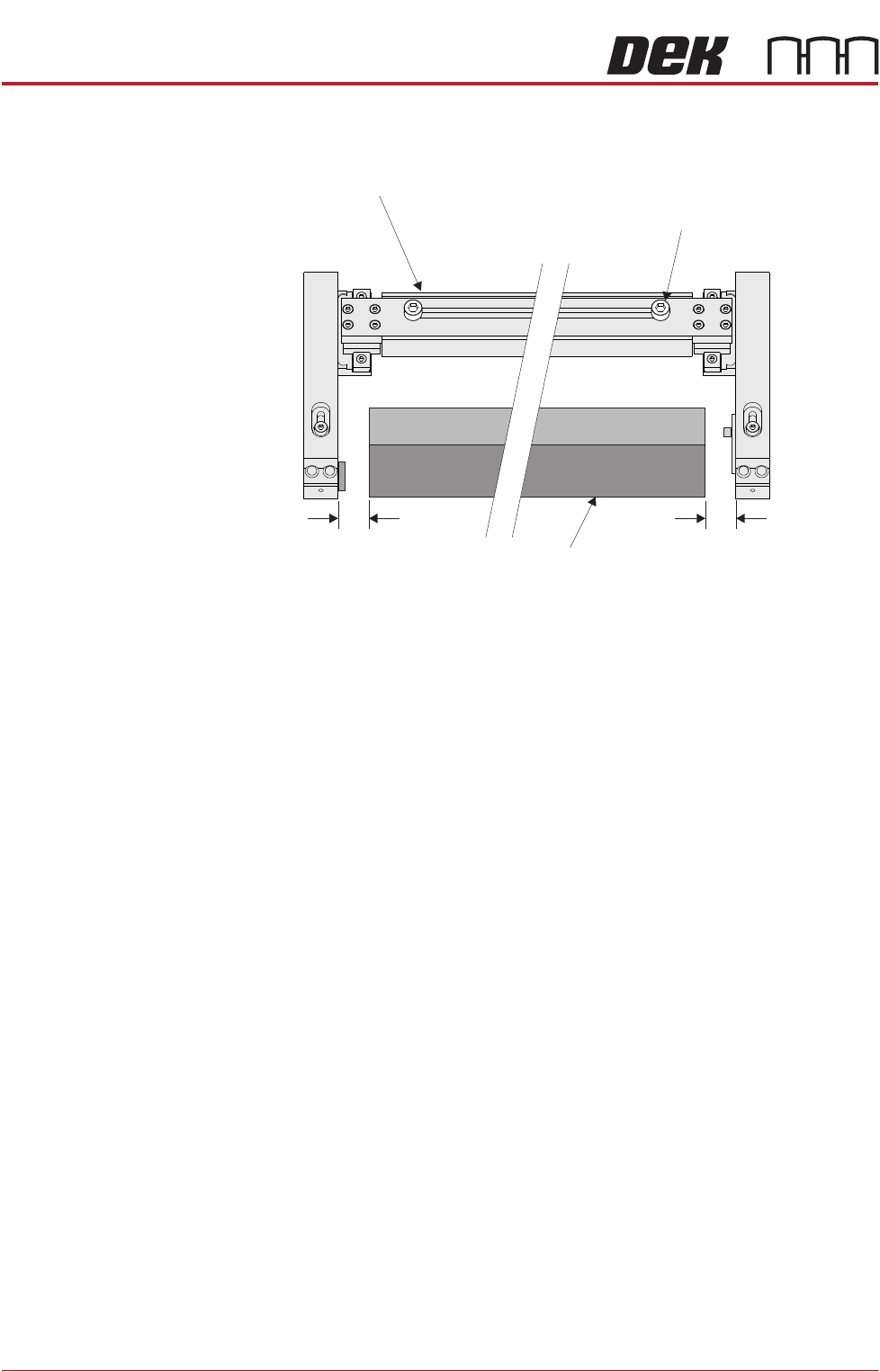
8. Set each arm to provide a gap between the edge of the squeegee (or
deflector) equal to 10mm.
9. Close the front printhead cover.
10. Press the System button.
11. Select Exit.
Roll Height Monitor
Width Adjustment
Securing Screw
(in 2 positions)
10mm 10mm
Front Squeegee
PASTE ROLL HEIGHT MONITOR
REPLACEMENT PROCEDURES
Chapter Issue 3, Aug 14 Technical Reference Manual 30.11
REPLACEMENT PROCEDURES
Fitment Carry out the following procedure to fit the Roll Height Monitor to the machine:
1. Ensure the machine is powered down.
2. Release the front squeegee thumbscrews and remove the front squeegee.
3. Remove the Squeegee ‘I‘Beam, use the three mounting screws for fitting the
roll height monitor.
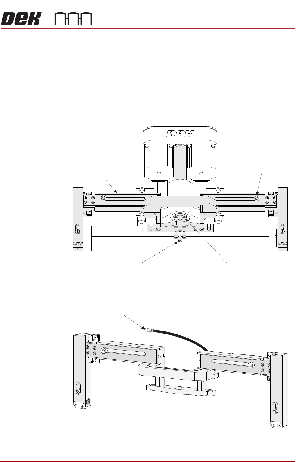
4. Fit the roll height monitor assembly to the front squeegee mounting plate
and secure with the three screws.
5. Connect the electrical connector 9PL60 to 9SK60.
6. Fit the front squeegee to the roll height monitor assembly.
Front Squeegee
Leadscrew
Roll Height Monitor
Width Adjustment
Securing Screw
(in 2 positions)
Front Squeegee Mount
‘I’ Beam Securing Screws
(in 3 positions)
Electrical Connector 9PL60
to Print Carriage IO Node 3

PASTE ROLL HEIGHT MONITOR
REPLACEMENT PROCEDURES
30.12 Technical Reference Manual Chapter Issue 3, Aug 14
7. On completion, power up and initialize the machine and carry out Squeegee
Reference Height setting.
Removal Carry out the following procedure to remove the Roll Height Monitoring from the
machine:
1. Ensure the machine is powered down.
2. Release the front squeegee thumbscrews and remove the front squeegee.
3. Disconnect the electrical connector 9PL60 from 9SK60.
4. Using a 4mm Allen key, loosen the three Roll Height Monitor assembly
securing screws and remove the monitor assembly from the machine.
5. Fit the front squeegee ‘I’ bar and secure with the three cap headed bolts and
refit the front squeegee to the front squeegee ‘I’ bar.
6. On completion, power up and initialize the machine and carry out Squeegee
Reference Height setting (see Squeegee Module, Infinity Technical Refer-
ence Manual for details).