192277 - Micron Technical Reference Volume 3.pdf - 第147页
RISING TABLE MODULE - STYLE 2 ADJUSTMENTS AND SETTINGS Chapter Issue 3, Feb 18 Technical Reference Manual 28.5 View on Rear of Rising T able Left Standard MTR Home V ane Home Sensor Home Sensor Home Sensor Securing Screw…
RISING TABLE MODULE - STYLE 2
ADJUSTMENTS AND SETTINGS
28.4 Techncial Reference Manual Chapter Issue 3, Feb 18
ADJUSTMENTS AND SETTINGS
Rising Table Home Setting
WARNING
HOT SURFACES. THE SURFACE OF THIS COMPONENT OR SURROUNDING
AREA MAY BECOME HOT DURING PROLONGED OPERATION. CARE TO BE
TAKEN WHEN WORKING IN THE VICINITY OF THIS COMPONENT.
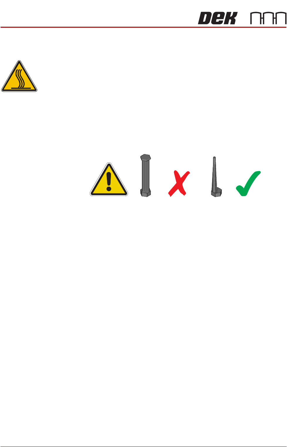
NOTE
1. 1. For MTR rail systems, the rails are fitted with a modular mid section.
MTR rails are deeper than the Standard system. The magnetic tooling pins
supplied with Standard rail systems must not be used with the MTR rail
system, as this may cause equipment damage.
2. 2. Due to the deeper rails being present on MTR systems, the rising table
height settings are different.
Two home sensor positions are available:
• Standard Home position (upper position)
• MTR Home position (lower position)
The procedure for changing the home sensor position should only be carried
out when switching between Standard and MTR options.
1. Power down the printer and fit a lock to the mains isolator lock out.
2. Gain access to the rising table motor.
3. Locate the home sensor.
4. Using a 2.5mm Allen key, undo the two home sensor securing screws.
5. Position the home sensor in the required location.
6. Fasten and tighten the two securing screws.
7. Turn the mains power ON.
8. Carry out the following calibrations:
• Vision Height, Camera System Module chapter refers
• Print Height, Calibrations section of this chapter refers
RISING TABLE MODULE - STYLE 2
ADJUSTMENTS AND SETTINGS
Chapter Issue 3, Feb 18 Technical Reference Manual 28.5
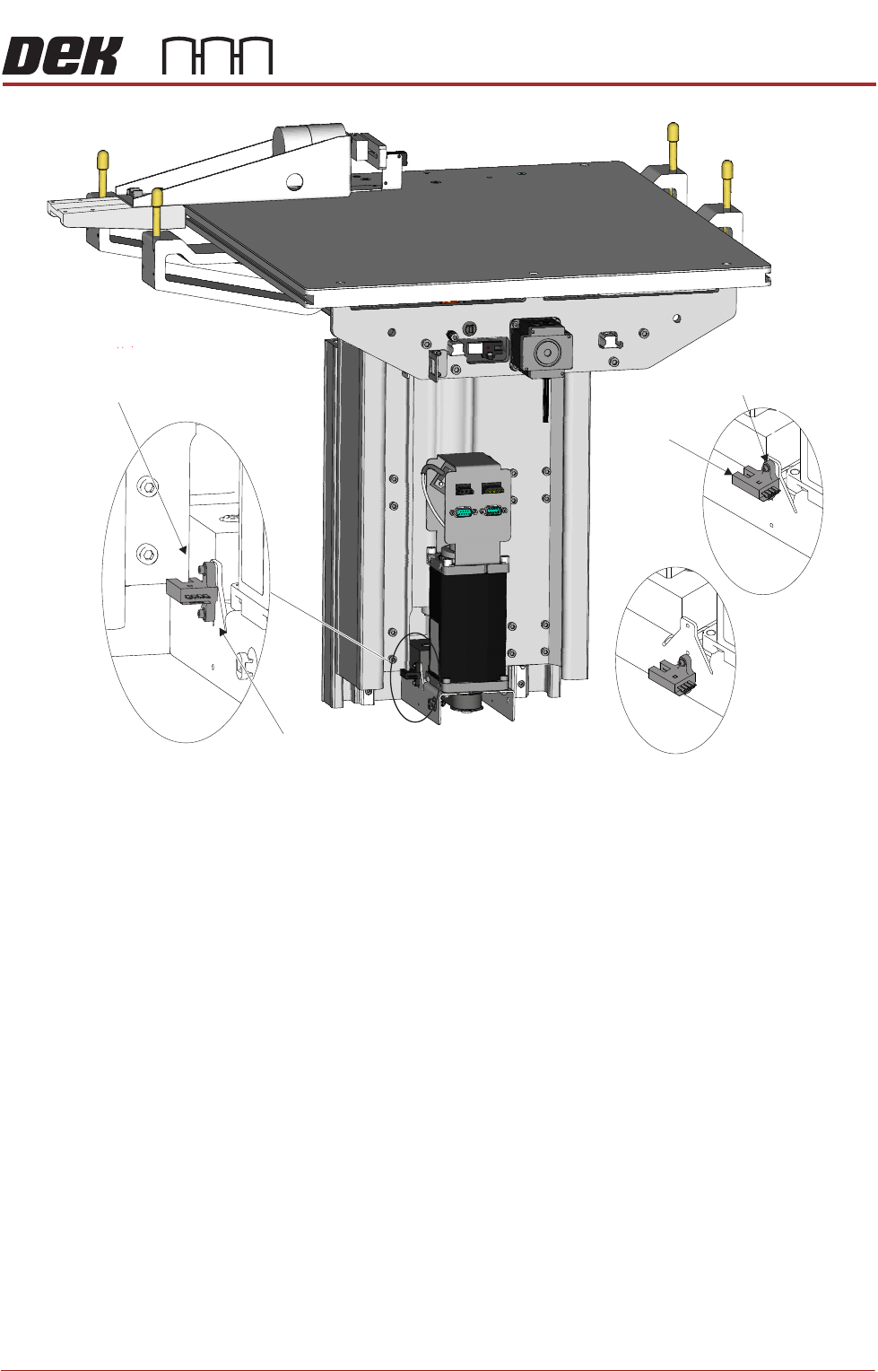
View on Rear of Rising TableLeft
Standard
MTR
Home Vane
Home Sensor
Home Sensor
Home Sensor
Securing Screws
RISING TABLE MODULE - STYLE 2
REPLACEMENT PROCEDURES
28.6 Techncial Reference Manual Chapter Issue 3, Feb 18
REPLACEMENT PROCEDURES
Rising Table Drive Belt
WARNING
HOT SURFACES. THE SURFACE OF THIS COMPONENT OR SURROUNDING
AREA MAY BECOME HOT DURING PROLONGED OPERATION. CARE TO BE
TAKEN WHEN WORKING IN THE VICINITY OF THIS COMPONENT.
1. Power down the printer and fit a lock to the mains isolator lock out.
2. Gain access to the rising table motor.
3. Using a 4mm Allen key, undo the three rising table motor securing screws.
4. Slide the rising table motor towards the leadscrew to slacken the drive belt.
5. Remove the drive belt and discard.
6. Fit the replacement drive belt.
7. Slide the rising table motor away from the leadscrew to tighten the drive belt
and ensure the motor is located correctly in the bracket cut out.
8. Whilst maintaining this tension, fasten and tighten the three rising table
motor securing screws.
9. Turn the mains power ON.
10. Carry out Rising Table Home Setting, Adjustments and Settings section of
this chapter refers.
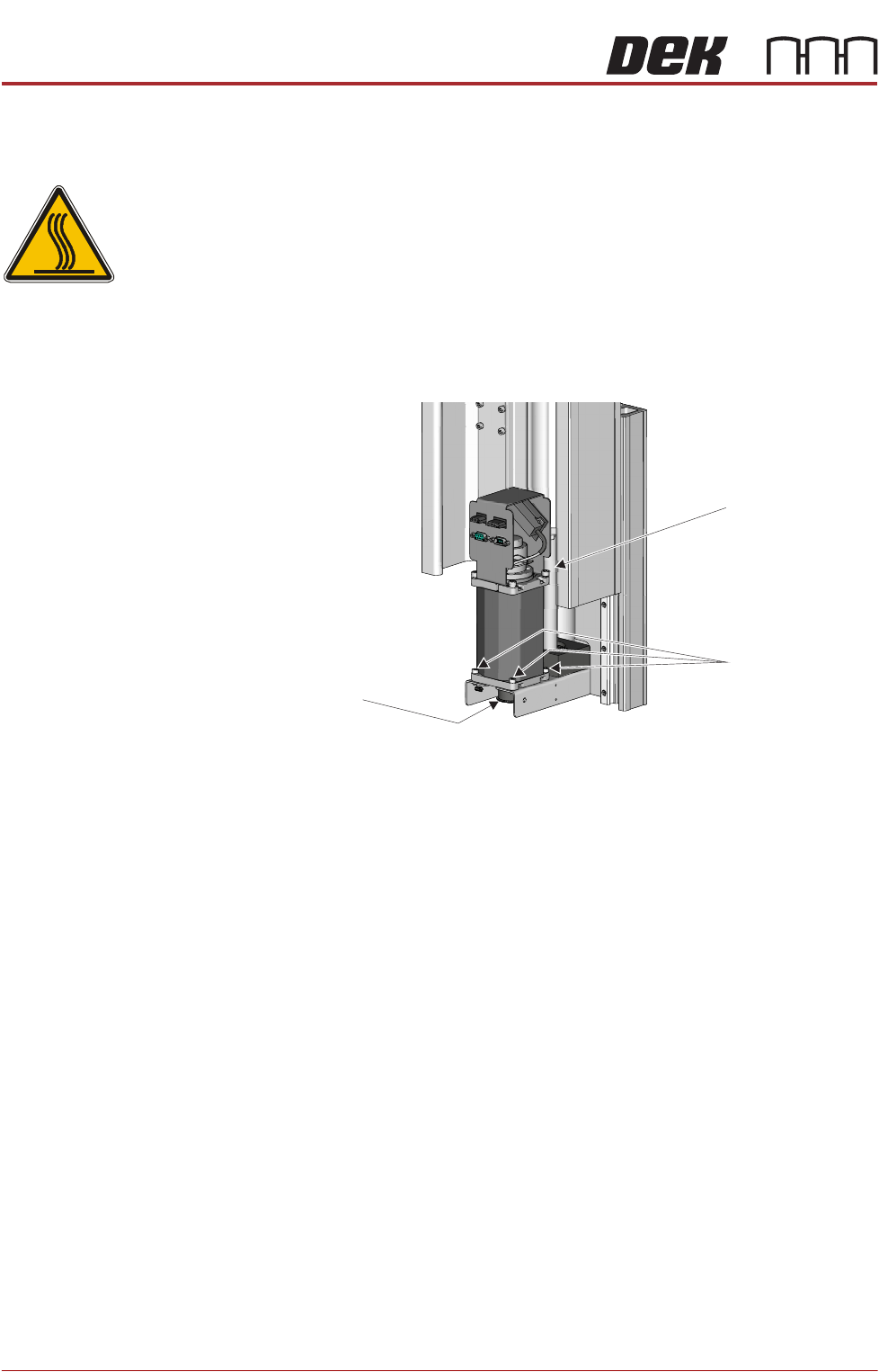
Leadscrew
Rising Table
Motor Securing
Screws
View From Rear of Rising Table Motor Assembly
Rising Table
Drive Belt