192277 - Micron Technical Reference Volume 3.pdf - 第36页
RAPID TRANSIT CONVEYOR (RTC) MODULE ADJUSTMENTS AND SETTINGS 22.24 Technical Reference Manual Chapter Issue 4, Aug 14 Sensitivity Adjustment The sensitivity setting of the senso rs is crit ical as it is important that th…
RAPID TRANSIT CONVEYOR (RTC) MODULE
ADJUSTMENTS AND SETTINGS
Chapter Issue 4, Aug 14 Technical Reference Manual 22.23
Board Ultra-sonic
Sensors
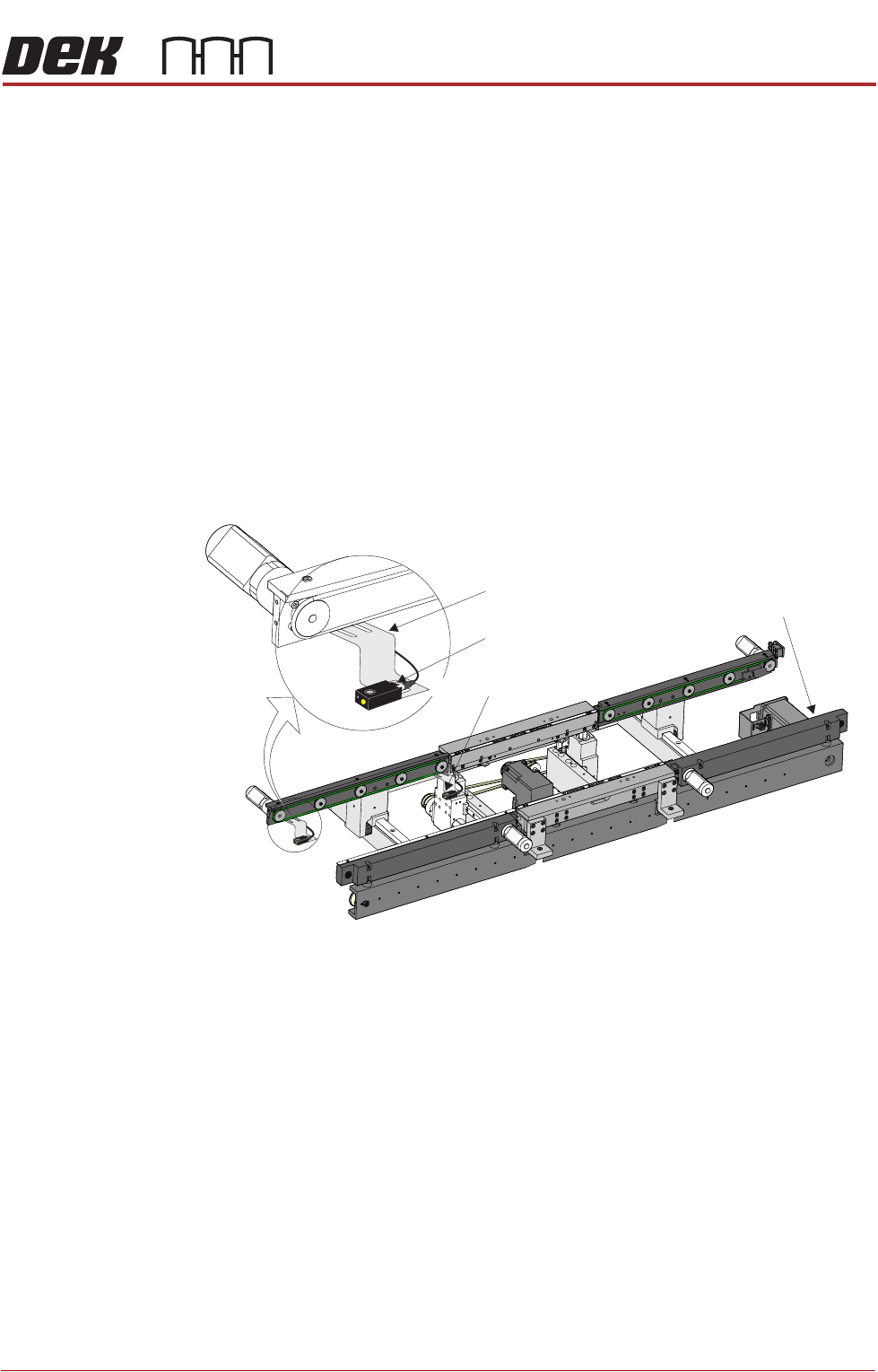
There are three board sensors:
• Board at Left Sensor
• Board at Stop Sensor
• Board at Right Sensor
Positional
Adjustment
The board sensors are adjustable in the X and Y directions to compensate for
any holes or cut-outs on the product board that coincide with the sensor when
the board is in the stopped position.
With the board in the stopped position over the sensor, if the sensor is not
seeing the board due to a hole or cut-out, use the following procedure to adjust
the sensor:
1. Power down the machine.
2. In the X direction; using a 2.5mm Allen key, loosen the two bolts that secure
the sensor to the bracket.
3. Move the sensor to the required position.
4. Tighten the two bolts that secure the sensor to the bracket.
5. In the Y direction; using a 2.5mm Allen key, loosen the two bolts that secure
the sensor bracket to the rails.
6. Move the sensor to the required position.
7. Tighten the two bolts that secure the sensor bracket to the rails.
8. Power up the machine and check for correct operation of the sensor.
View on Front of RTC System
Board at Right Sensor
Board at Left Sensor
Sensor Bracket
Board at Stop Sensor
RAPID TRANSIT CONVEYOR (RTC) MODULE
ADJUSTMENTS AND SETTINGS
22.24 Technical Reference Manual Chapter Issue 4, Aug 14
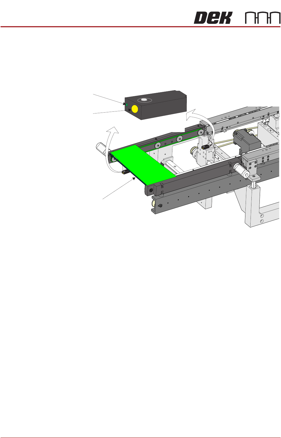
Sensitivity
Adjustment
The sensitivity setting of the sensors is critical as it is important that the sensor
is only activated by the board and not machine parts.
To achieve an optimum setting carry out the following procedure:
1. Press the yellow Set button on the sensor for approximately two seconds.
The green LED comes On.
2. Place a board on the rails above the belts.
3. Press the yellow Set button again. The green LED comes On again.
4. Remove the board from the rails and confirm that the green LED is Off.
5. Place the board on the belts and above the sensor. The green LED should
be On. Remove the board and place it back on top of the rail as in Step 2.
The green LED should be Off. This confirms that the sensor is correctly set.
NOTE
If the sensor fails to set correctly it may need to be reset. Disconnect the power
from the sensor by unscrewing the plug at the back. Reconnect the plug and
press Set for approximately ten seconds; the LED flashes rapidly. The sensor
is now reset and the procedure above can be followed to set the sensitivity.
View on Inroad Conveyor of RTC System
Set Button
LED
Board
Set
Sensor
(also at outroad conveyor)
RAPID TRANSIT CONVEYOR (RTC) MODULE
REPLACEMENT PROCEDURES
Chapter Issue 4, Aug 14 Technical Reference Manual 22.25
REPLACEMENT PROCEDURES
Board Clamp Replacement
WARNING
BOARD CLAMPS. EXTREME CARE MUST BE EXERCISED WHEN WORKING IN
THE TOOLING AREA OF THE MACHINE TO AVOID INJURY. THE FOILS ON THE
FRONT AND REAR BOARD CLAMPS ARE VERY SHARP.
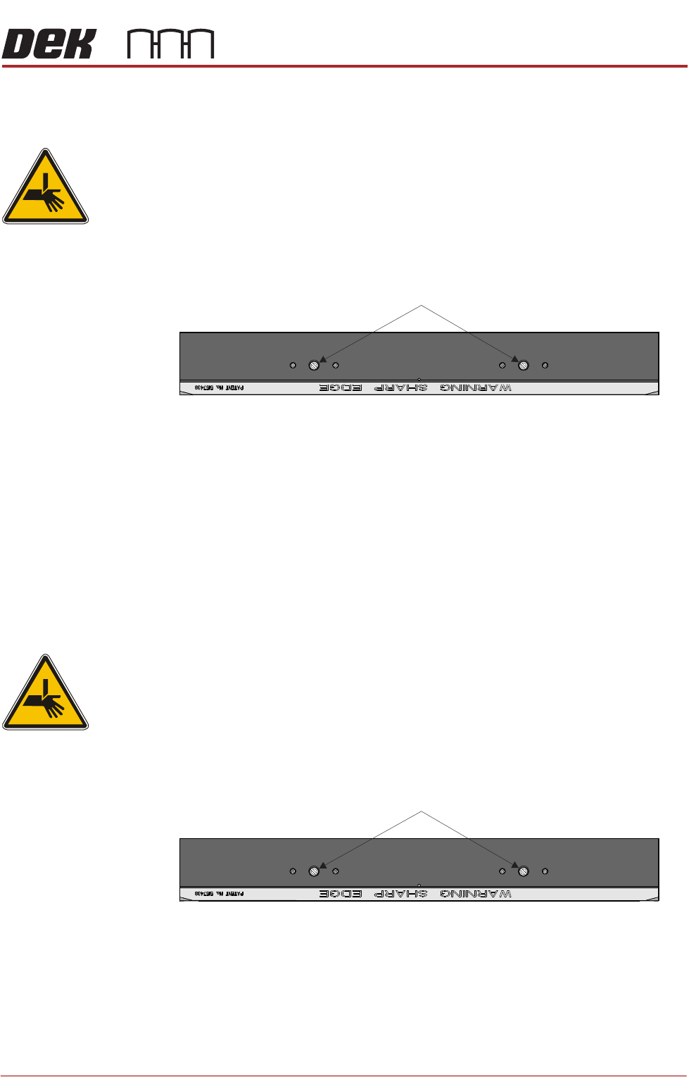
1. Remove the two board clamp securing screws using a flat bladed screw-
driver.
2. Lift the board clamp off the rail.
3. Fit the new board clamp to the print station rail.
4. Pushing the board clamp towards the other rail, refit the screws removed in
Step 1.
NOTE
The Board Clamp Setting procedure is not required after board clamp
replacement.
Board Clamp Foil Replacement
WARNING
BOARD CLAMPS. EXTREME CARE MUST BE EXERCISED WHEN WORKING IN
THE TOOLING AREA OF THE MACHINE TO AVOID INJURY. THE FOILS ON THE
FRONT AND REAR BOARD CLAMPS ARE VERY SHARP.
1. Remove the two board clamp securing screws using a flat bladed screw-
driver.
2. Lift the board clamp off the rail and turn upside down on a solid surface.
3. Using a 2mm Allen key, remove the 6 cap head screws that secure the foil
to the board clamp.
4. Fit the new foil with the screws removed in Step 3.
Plan View of Print Station Rail
Board Clamp Securing Screws
Plan View of Print Station Rail
Board Clamp Securing Screws