192277 - Micron Technical Reference Volume 3.pdf - 第161页
BOARD SUPPORT TO OLING MODULE GRID-LOK TOOLING Chapter Issue 7, Jan 15 Technical Reference Manual 29.9 Electrical Schematic Programmable Interrupt Controller (PIC) Board Solenoid 1 () Raise T ooling Pins Solenoid 2 (Lock…

BOARD SUPPORT TOOLING MODULE
GRID-LOK TOOLING
29.8 Technical Reference Manual Chapter Issue 7, Jan 15
The Grid-Lok tooling system can be configured to handle the following board
sizes:
• Minimum board size - 38mm x 50mm
• Maximum board size - 254mm x 508mm
• Board thickness - 0.4mm - 5.0mm
With the board loaded and raised to print height, all the Grid-Lok pins are
extended using pneumatic pressure until they meet the underside of the board,
stencil or component. After a set period of time, the locking mechanisms of the
tooling modules are activated and the pins remain in this position until the
system is reset.
The Grid-Lok system incorporates two modes of operation, manual or auto-
matic.
In manual mode, the tooling pins conform to the board profile and remain in that
position until the reset button is pressed.
In automatic mode, the tooling pins conform to each board before it is printed.
BOARD SUPPORT TOOLING MODULE
GRID-LOK TOOLING
Chapter Issue 7, Jan 15 Technical Reference Manual 29.9
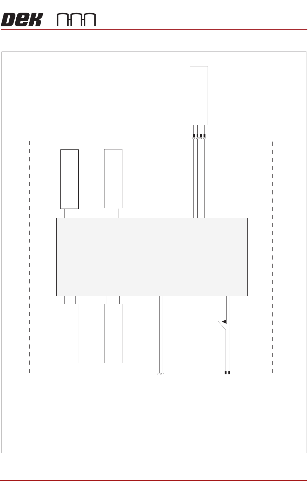
Electrical Schematic
Programmable Interrupt
Controller (PIC) Board
Solenoid 1
()Raise Tooling Pins
Solenoid 2
(Lock )Tooling Pins
Selector Switch
Board Clamp Switch
Power Switch
Operator Interface
Grid-Lok Control Unit
Power Suppl
y Input
(M37 Power Suppl
y Module)
Machine Software Input
(Node Board 2)
BOARD SUPPORT TOOLING MODULE
GRID-LOK TOOLING
29.10 Technical Reference Manual Chapter Issue 7, Jan 15
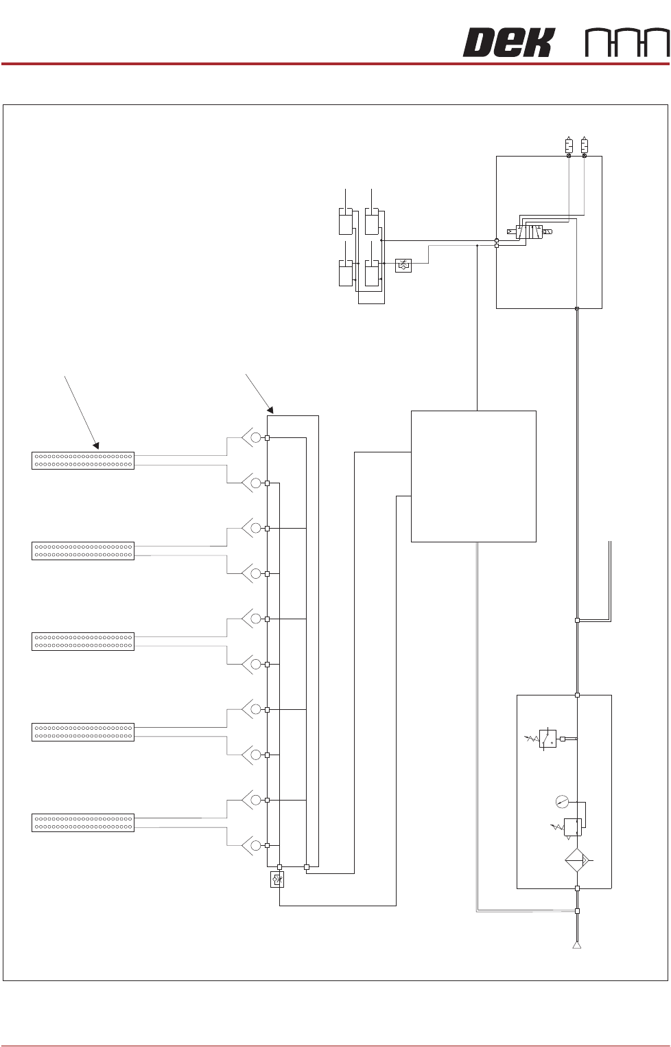
Pneumatic Schematic
Tooling Modules
Grid-Lok Manifold
Grid-Lok Control Unit
P
Pressure
Sense
Filter/Reg Assy
Mains Air to Machine
A
B
5/2
Pos 7
Board Clamps
Pneumatic Manifold (part of)
Mains
Air In
At 4.5 Bar
Minimum