192277 - Micron Technical Reference Volume 3.pdf - 第47页
CAMERA SYSTE M MODULE ELECTRICAL SCHEMATIC Chapter Issue 9, Feb 18 Technical Reference Manual 23.5 Figure 23-4 Linear Drive Schematic PC P C I B u s Motherboard USB M36 Machine Control Enclosure NextMove Interface NextMo…
CAMERA SYSTEM MODULE
ELECTRICAL SCHEMATIC
23.4 Technical Reference Manual Chapter Issue 9, Feb 18
ELECTRICAL SCHEMATIC
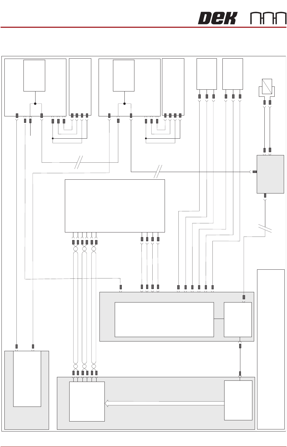
Figure 23-3 Rotary Drive Schematic
M37 Power Supply Module
Power Distribution
PCB
CAN Terminator
N8SK2
Camera X Motor
Node 8
M37PL18
Servo DC Supply & 24V US (Motor Logic)
N8PL1
N8PL4
DIG IN 2
DIG IN 2
0V
0V
Signal
Signal
24V
24V
(L)
(L)
Camera X
Home 10SE01
Fork Opto
CAN
Encoder/
Decoder
N8SK3
CAN In
Camera Y Motor
Node 9
N9PL1
N9PL4
Camera Y
Home 10SE02
Fork Opto
CAN
Encoder/
Decoder
N9SK3
CAN In
CAN Out
M37PL19
PC
P
C
I
B
u
s
Motherboard
USB
Servo DC Supply & 24V US (Motor Logic)
N9SK2
M36 Machine
Control Enclosure
NextMove
Interface
NextMove ES
(I/O Node 1)
M36PL35
CAN Bus
Main Machine
I/O Node 2
N2SK2
CAN In
16SK14
16SOL14
Board
Stop
DIG OUT 10
N2PL4
0V
CAN
Out
N2SK3
Board Stop
Extended
10SE20
Board At
Stop
10SE07
10SK24
M36PL11
0V
+12V
DIG IN 8
+12V
0V
DIG IN 9
NOTE
The breaks in the CAN Bus chain reflect that additional I/O Nodes
may be fitted, refer to Machine Control chapter for the complete
CAN Bus chain.
Power
3PL55
GND
TP B-
TP B+
TP A-
TP A+
Digital
Camera
10PL17
10SK13
PCI Interface
Card
M36PL16
M36PL5
Trigger
0V
+24V US
0V
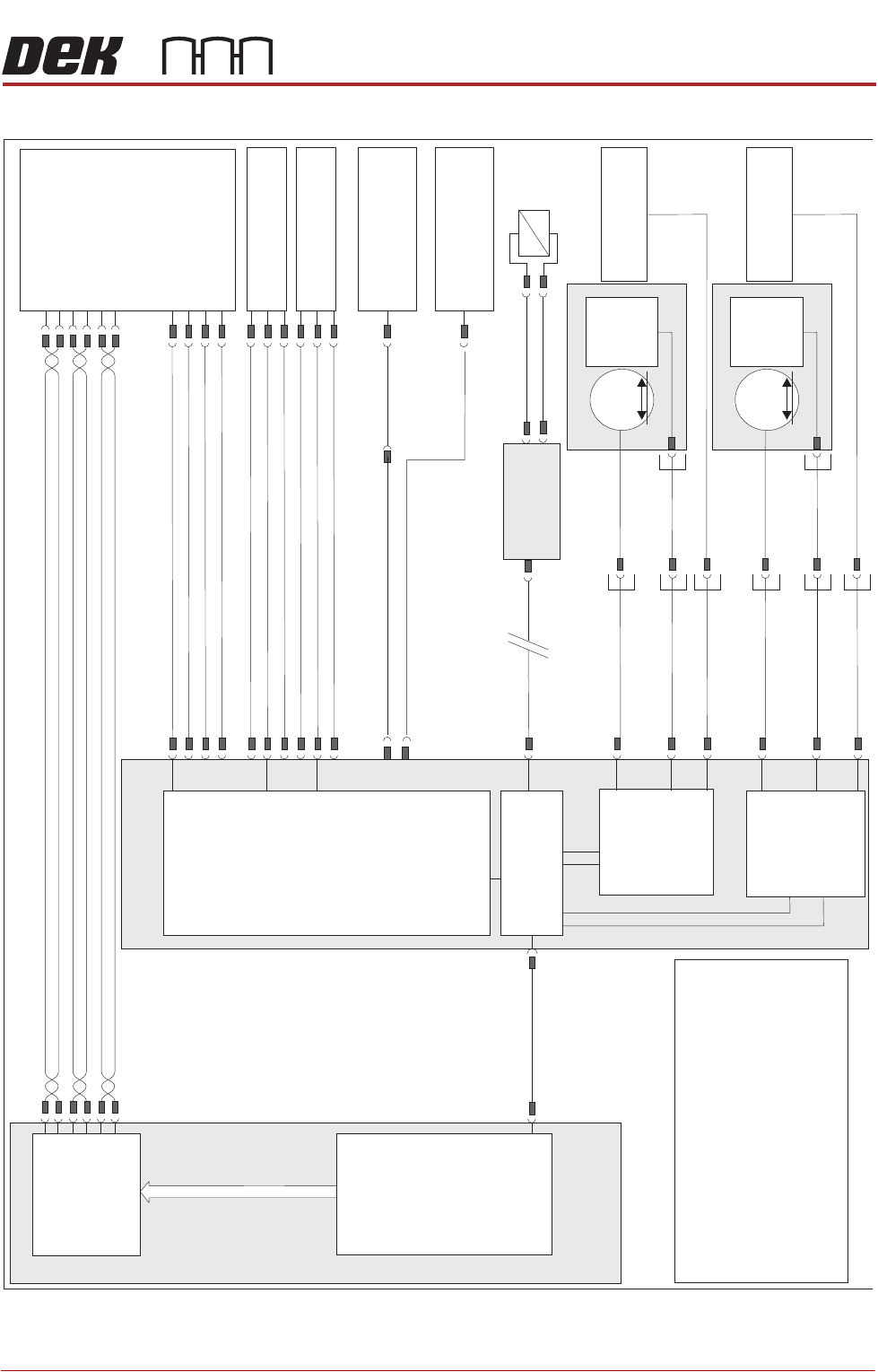
CAMERA SYSTEM MODULE
ELECTRICAL SCHEMATIC
Chapter Issue 9, Feb 18 Technical Reference Manual 23.5
Figure 23-4 Linear Drive Schematic
PC
P
C
I
B
u
s
Motherboard
USB
M36 Machine
Control Enclosure
NextMove
Interface
NextMove ES
(I/O Node 1)
M36PL35
CAN Bus
Main Machine
I/O Node 2
N2SK2
CAN In
16SK14
16SOL14
Board
Stop
DIG OUT 10
N2PL4
0V
Board Stop Extended
10SE20
Board At Stop
10SE07
10SK24
M36PL11
0V
+12V
DIG IN 8
+12V
0V
DIG IN 9
NOTE
The breaks in the CAN Bus chain reflect1.
that additional I/O Nodes may be fitted,
refer to Machine Control chapter for the
complete CAN Bus chain.
2. HawkEye encoder edge connector is
fitted to Axis 0 (M36PL06) when the
HawkEye option is used.
3. Camera encoders are reverse wired.
Motor
3~
Hall W+
Hall V+
Hall U+
X Linear Motor
10SK29
Camera X Encoder
10EN1
Camera Y Home
10SE02
10SE02
8PL27
M36PL19
M36PL15
Camera X Home
10SE01
10SE01
EuroFlex
Axis 0
M36PL07
M36PL06
M36PL05
A OUT 0
10SK37
10SK31
Motor
3~
Hall W+
Hall V+
Hall U+
Y Linear Motor
10SK30
Camera Y Encoder
10EN2
M36PL03
M36PL02
10SK38
10SK32
M36PL01
EuroFlex
Axis 1
A OUT 1
Digital Camera
3PL55
Power
GND
TP B-
TP B+
TP A-
TP A+
10PL17
M36PL16
Trigger
0V
+24V US
0V
10SK13
PCI Interface
Card
10SK33
10SK34
See Note 2
CAMERA SYSTEM MODULE
ADJUSTMENTS AND SETTINGS
23.6 Technical Reference Manual Chapter Issue 9, Feb 18
ADJUSTMENTS AND SETTINGS
X Camera Home
Positioning
The position of the sensor and vane is fixed, therefore no adjustment is
possible.
Y Camera Home
Positioning
The position of the sensor and vane is fixed, therefore no adjustment is
possible.
X Axis Parallelism
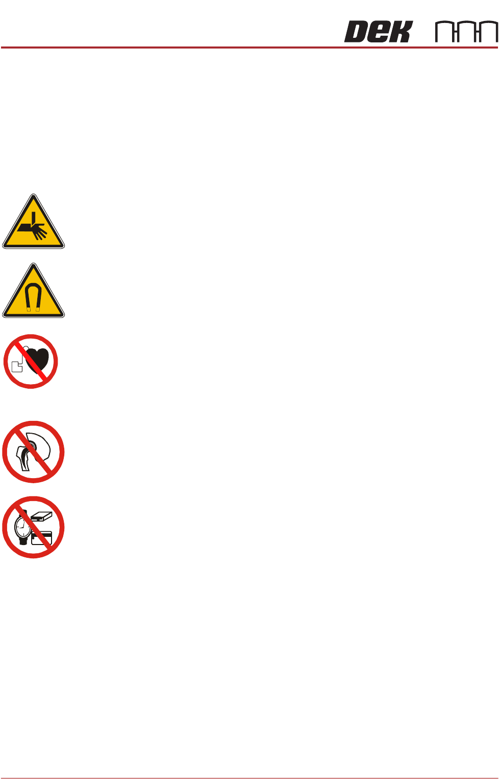
WARNING
BOARD CLAMPS. EXTREME CARE MUST BE EXERCISED WHEN WORKING IN
THE TOOLING AREA OF THE MACHINE TO AVOID INJURY. THE FOILS ON THE
FRONT AND REAR BOARD CLAMPS ARE VERY SHARP.
WARNING
STRONG MAGNET FIELD. A STRONG MAGNETIC FIELD EXISTS IN THE
VICINITY OF THIS LABEL. THIS MAY PRESENT A HAZARD TO PERSONNEL OR
EQUIPMENT.
))
((
PROHIBITION
ELECTROMAGNETIC FIELD. AN ELECTROMAGNETIC FIELD EXISTS WITHIN
THE MACHINE FROM THE LINEAR MOTORS. THESE MAY PRESENT A HAZARD
TO PEOPLE FITTED WITH AN IMPLANTED CARDIAC DEVICE. THE MOTOR
MANUFACTURER RECOMMENDS A SAFE DISTANCE OF AT LEAST 15MM.
PROHIBITION
ELECTROMAGNETIC FIELD. AN ELECTROMAGNETIC FIELD EXISTS WITHIN
THE MACHINE FROM THE LINEAR MOTORS. THESE MAY PRESENT A HAZARD
TO PEOPLE FITTED WITH AN IMPLANTED CARDIAC DEVICE. THE MOTOR
MANUFACTURER RECOMMENDS A SAFE DISTANCE OF AT LEAST 15MM.
PROHIBITION
STRONG MAGNETIC FIELD. A STRONG MAGNETIC FIELD EXISTS IN THE
VICINITY OF THE LINEAR MOTORS THAT REPRESENT A SERIOUS HAZARD TO
PEOPLE FITTED WITH METALLIC IMPLANTS.
PROHIBITION
STRONG MAGNETIC FIELD. A STRONG MAGNETIC FIELD EXISTS IN THE
VICINITY OF THE LINEAR MOTORS THAT MAY ACT UPON FERROUS OBJECTS
WHOSE MOVEMENTS COULD LEAD TO PERSONAL INJURY AND/OR DAMAGE
TO THE MACHINE.
NOTE
The X axis parallelism is factory set and shouldn’t normally need to be adjusted.
1. Select Open Cover Commands.
2. Select Carriage To Rear.
3. Select Unload Screen.
4. Open the front printhead cover.
5. Remove the stencil from the machine.
6. Close the front printhead cover.
7. Press the System button.
8. Select Back.