192277 - Micron Technical Reference Volume 3.pdf - 第68页
CAMERA SYSTEM MODULE REPLACEMENT PROCEDURES 23.26 Technical Reference Manual Chapter Issue 9, Feb 18 25. Remove the timing belt clamp securing screws one at a time, apply a suitable locking compound and fully tighten . 2…
CAMERA SYSTEM MODULE
REPLACEMENT PROCEDURES
Chapter Issue 9, Feb 18 Technical Reference Manual 23.25
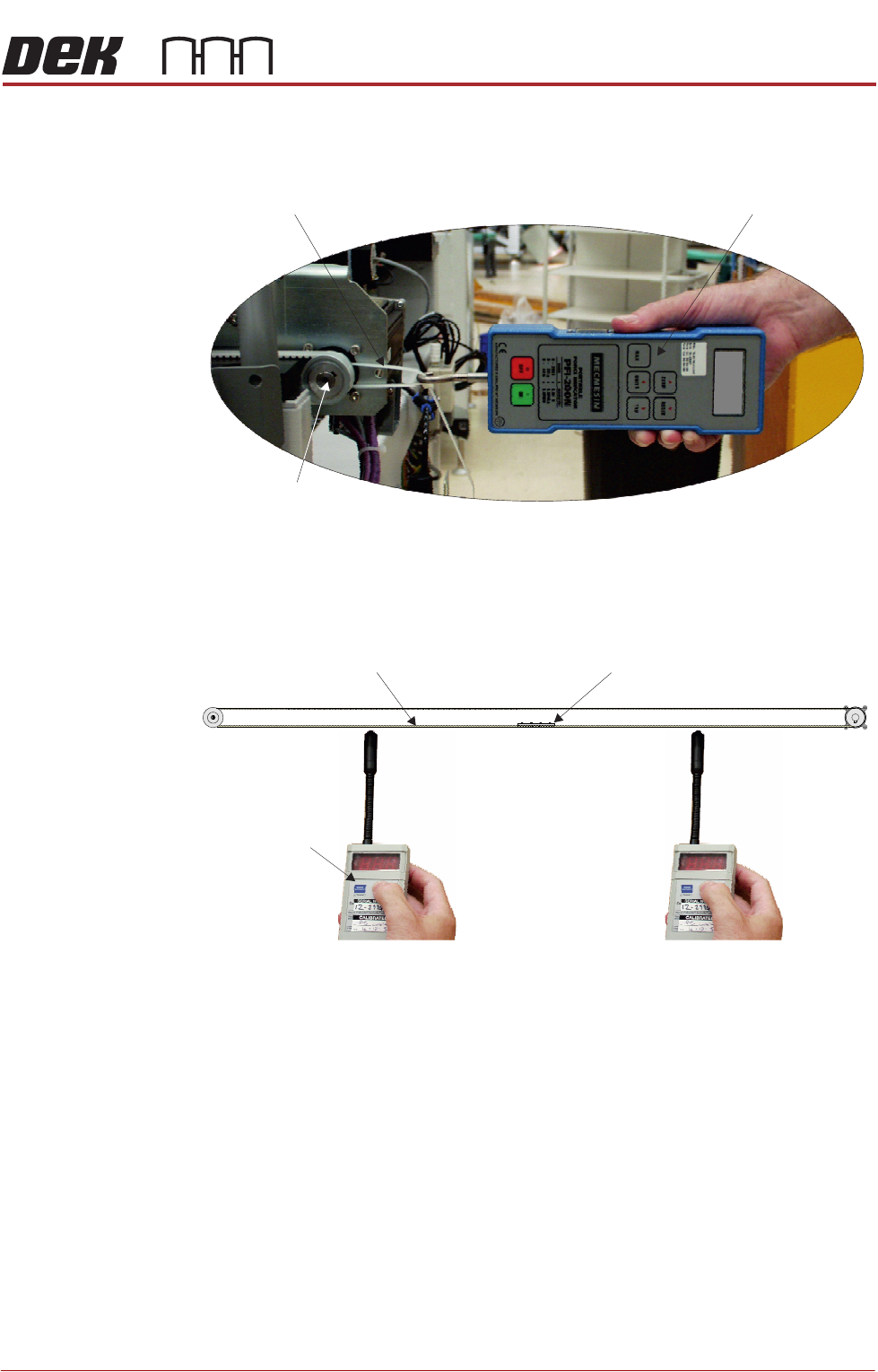
16. Using a suitable cable tie, engage a forcemeter across the motor pulley.
Apply a horizontal force of 24kg to the belt. Maintaining this force, tighten
the two securing screws.
17. Remove the forcemeter. Do not remove the cable tie as further adjustment
may be necessary.
18. Ensure that the belt clamp is midway between the two pulleys.
19. Using a tension meter (Part No. 190279), check the timing belt tension either
side of the cable clamp is between 42Hz and 48Hz. Check the two readings
are within 1Hz of each other.
NOTE
Adjust the position (between the two pulleys) of the belt clamp to achieve
the 1Hz deviation.
20. If adjustment is not required, go to Step 25.
21. If adjustment is required, slacken the two securing screws as detailed in
Step 9.
22. Adjust the timing belt tension using the cable tie.
23. Tighten the locknut.
24. Repeat Steps 19 to 23 until the correct tension is achieved.
Forcemeter
Cable Tie
View on Right Hand Side of Machine
Motor Pulley
24.0 kg
Timing Belt ClampTiming Belt
Tension Meter
Position A (mid span) Position B (mid span)

CAMERA SYSTEM MODULE
REPLACEMENT PROCEDURES
23.26 Technical Reference Manual Chapter Issue 9, Feb 18
25. Remove the timing belt clamp securing screws one at a time, apply a
suitable locking compound and fully tighten.
26. Remove the cable tie.
27. Refit the panels removed in Step 8.
28. Power up the machine.
29. Select Maintenance.
30. Select Diagnostics.
31. Use Next or Previous to highlight Camera Axes.
32. Select Select Module.
33. Use Next or Previous to highlight Home Camera X Axis.
34. Select Run Diagnost.
35. Use Next or Previous to highlight Home Camera Y Axis.
36. Select Run Diagnost.
37. Carry out the following checks:
a. Camera Reference Position.
b. Calibrate Vision.
Replacing the Encoder and Encoder Strip (Linear Servo Motor Systems Only)
If the encoder or encoder strip needs to be replaced, there is a special tool kit
available which is used to maintain the correct alignment. The tool kit uses a
scale applicator, this temporarily replaces the encoder for laying the encoder
strip.
The encoder set up involves setting the height and yaw correctly so that the
encoder travels at the focused distance for reliable reading.
The tool kit is available from ASM Customer Support Group, contact the help
desk for details.

CAMERA SYSTEM MODULE
CALIBRATIONS AND CHECKS
Chapter Issue 9, Feb 18 Technical Reference Manual 23.27
CALIBRATIONS AND CHECKS
Board Stop X Offset Check
WARNING
BOARD CLAMPS. EXTREME CARE MUST BE EXERCISED WHEN WORKING IN
THE TOOLING AREA OF THE MACHINE TO AVOID INJURY. THE FOILS ON THE
FRONT AND REAR BOARD CLAMPS ARE VERY SHARP.
PROHIBITION
STRONG MAGNETIC FIELD. A STRONG MAGNETIC FIELD EXISTS IN THE
VICINITY OF THE LINEAR MOTORS THAT MAY ACT UPON FERROUS OBJECTS
WHOSE MOVEMENTS COULD LEAD TO PERSONAL INJURY AND/OR DAMAGE
TO THE MACHINE.
1. Select Open Cover Commands.
2. Select Carriage To Rear.
3. Select Unload Screen.
4. Open the front printhead cover.
5. Remove the stencil.
6. Close the front printhead cover.
7. Press the System button.
8. Select Back.
9. Select Maintenance.
10. Select Diagnostics.
11. Use Next or Previous to highlight Camera Axes.
12. Select Select Module.
13. Use Next or Previous to highlight Home Camera X Axis.
14. Select Run Diagnost.
15. Use Next or Previous to highlight Home Camera Y Axis.
16. Select Run Diagnost.
17. Use Next or Previous to highlight Drive to Board Stop Position.
18. Select Run Diagnost.
19. Select Exit.
20. Use Next or Previous to highlight Rail System.
21. Select Select Module.
22. Use Next or Previous to highlight Toggle Board Stop.
23. Select Run Diagnost.
24. Open the front printhead cover.
25. Place a board onto the rails and move it up against the board stop.
26. Close the front printhead cover.
27. Press the System button.
28. Use Next or Previous to highlight Toggle Board Clamp.