192277 - Micron Technical Reference Volume 3.pdf - 第54页
CAMERA SYSTEM MODULE ADJUSTMENTS AND SETTINGS 23.12 Technical Reference Manual Chapter Issue 9, Feb 18 Magnet T rack and Forcer Assembly Settings (Linear Servo Motor Systems Only) W ARNING BOARD CLAMPS. EXTREME CA RE MUS…
CAMERA SYSTEM MODULE
ADJUSTMENTS AND SETTINGS
Chapter Issue 9, Feb 18 Technical Reference Manual 23.11
44. Loosen the two securing screws at each end of the camera X axis support
platform.
45. Using a soft headed mallet gently tap the edge of the camera X axis support
platform to close the gap on the camera alignment pins.
NOTE
The camera can be severely damaged if excessive force is used to position
the camera axis.
46. Tighten the two securing screws at each end of the camera X axis support
platform, taking care not to allow the position to slip.
47. Check for parallelism again.
48. Remove the location jig from the rising table.
49. Fit the board clamp to the front rail.
50. Refit the stencil.
51. Close the front printhead cover.
52. Press the System button.
53. Select Exit.
54. Select Exit.
55. Select Back.
Y Axis Parallelism The Y axis parallelism for both rotary and linear motor machines is factory set
and is not adjustable.
View on Arrow A
A
Securing Screws Securing Screws

CAMERA SYSTEM MODULE
ADJUSTMENTS AND SETTINGS
23.12 Technical Reference Manual Chapter Issue 9, Feb 18
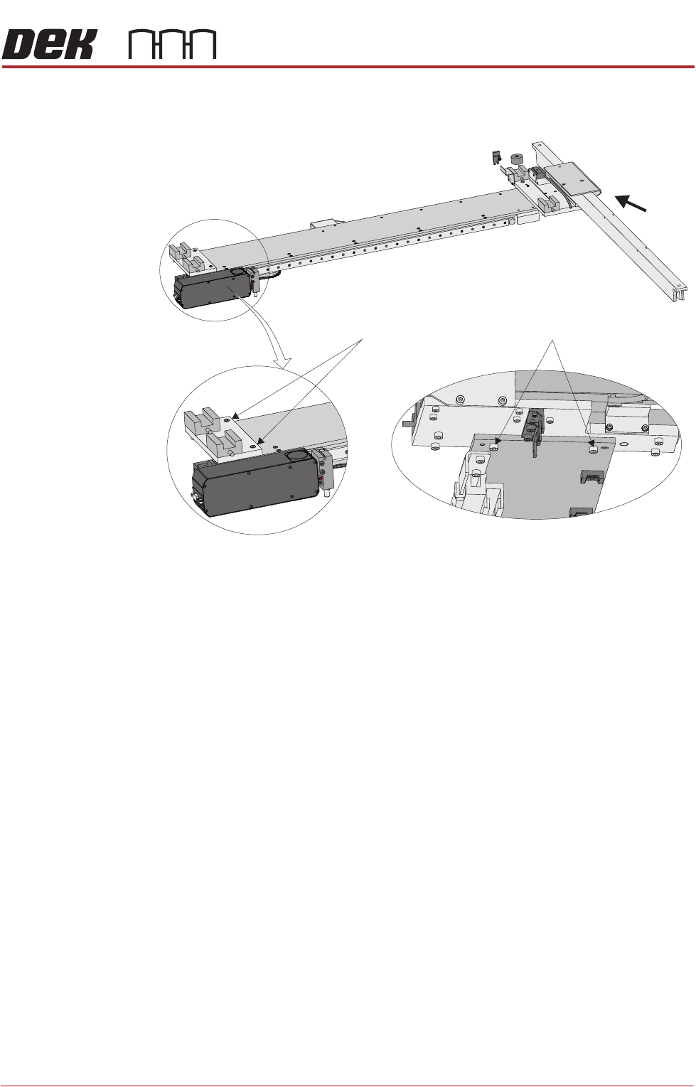
Magnet Track and Forcer Assembly Settings (Linear Servo Motor Systems Only)
WARNING
BOARD CLAMPS. EXTREME CARE MUST BE EXERCISED WHEN WORKING IN
THE TOOLING AREA OF THE MACHINE TO AVOID INJURY. THE FOILS ON THE
FRONT AND REAR BOARD CLAMPS ARE VERY SHARP.
WARNING
STRONG MAGNET FIELD. A STRONG MAGNETIC FIELD EXISTS IN THE
VICINITY OF THIS LABEL. THIS MAY PRESENT A HAZARD TO PERSONNEL OR
EQUIPMENT.
))
((
PROHIBITION
ELECTROMAGNETIC FIELD. AN ELECTROMAGNETIC FIELD EXISTS WITHIN
THE MACHINE FROM THE LINEAR MOTORS. THESE MAY PRESENT A HAZARD
TO PEOPLE FITTED WITH AN IMPLANTED CARDIAC DEVICE. THE MOTOR
MANUFACTURER RECOMMENDS A SAFE DISTANCE OF AT LEAST 15MM.
PROHIBITION
ELECTROMAGNETIC FIELD. AN ELECTROMAGNETIC FIELD EXISTS WITHIN
THE MACHINE FROM THE LINEAR MOTORS. THESE MAY PRESENT A HAZARD
TO PEOPLE FITTED WITH AN IMPLANTED CARDIAC DEVICE. THE MOTOR
MANUFACTURER RECOMMENDS A SAFE DISTANCE OF AT LEAST 15MM.
PROHIBITION
STRONG MAGNETIC FIELD. A STRONG MAGNETIC FIELD EXISTS IN THE
VICINITY OF THE LINEAR MOTORS THAT REPRESENT A SERIOUS HAZARD TO
PEOPLE FITTED WITH METALLIC IMPLANTS.
PROHIBITION
STRONG MAGNETIC FIELD. A STRONG MAGNETIC FIELD EXISTS IN THE
VICINITY OF THE LINEAR MOTORS THAT MAY ACT UPON FERROUS OBJECTS
WHOSE MOVEMENTS COULD LEAD TO PERSONAL INJURY AND/OR DAMAGE
TO THE MACHINE.
Setting the Forcer
Air Gap
The forcer unit comprises electrical windings encapsulated in an epoxy insula-
tion. If the unit is offset it may rub against the side wall of the magnet track. To
prevent this an air gap of 0.5mm on both sides of the forcer unit should be
maintained.
1. Select Maintenance.
2. Select Diagnostics.
3. Use Next or Previous to highlight Camera Axes.
4. Select Select Module.
5. Ensure that Home Camera X Axes is highlighted.
6. Select Run Diagnost.
7. Use Next or Previous to highlight Home Camera Y Axes.
8. Select Run Diagnost.
9. Select Exit.
10. Select Exit.
11. Select Back.
12. Select Shut Down.
13. Select Continue.
14. Switch the mains isolator to OFF.
CAMERA SYSTEM MODULE
ADJUSTMENTS AND SETTINGS
Chapter Issue 9, Feb 18 Technical Reference Manual 23.13
15. Open the front printhead cover.
16. Remove the stencil.
X Axis 17. Remove the left side panel.
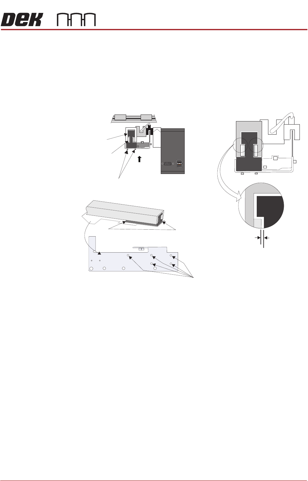
18. Using a 0.5mm shim on the left hand end of the magnet track, ensure that
the air gap between the forcer and the magnet track is equal on both the left
and right side of the forcer.
19. Manually move the camera to the right hand side of the machine and repeat
Step 18 for the right hand end of the magnet track.
20. If the alignment is correct, go to Step 24.
21. From the underside of the assembly locate the five magnet track adjustment
screws. Slacken the screws but do not remove. Gently move the bracket
in the direction required for the 0.5mm shim to fit comfortably all around.
Tighten the screws to secure.
22. Check the air gap again to ensure that the screws have all been tightened
evenly without misaligned the forcer.
23. Slide the camera assembly along the whole length of the X camera axis and
ensure there are no points where the forcer contacts the magnet track side
wall.
24. Refit the left side panel.
Y Axis 25. Remove the right side panel.
26. Manually move the camera support beam to a central position where access
to the unit can be readily gained.
27. Using a 0.5mm shim on the front end of the magnet track, ensure that the
Forcer to Magnet Track
Air Gap (both sides)
0.5mm Min
Magnet Track Adjustment Screws (3mm)
Test both gaps on
both ends of the
forcer
Camera at Home
Magnet Track Adjustment Screws (5 off)
A
View on Arrow A
Camera Mount
X Forcer
X Magnet Track
Y Linear Rail