192277 - Micron Technical Reference Volume 3.pdf - 第168页
BOARD SUPPORT TO OLING MODULE REPLACEMENT PROCEDURES 29.16 Technical Reference Manual Chapter Issue 7, Jan 15 Removing Grid- Lok T ooling W ARNING BOARD CLAMPS. EXTREME CA RE MUST BE EXERCIS ED WHEN WORKING IN THE TOOLIN…
BOARD SUPPORT TOOLING MODULE
REPLACEMENT PROCEDURES
Chapter Issue 7, Jan 15 Technical Reference Manual 29.15
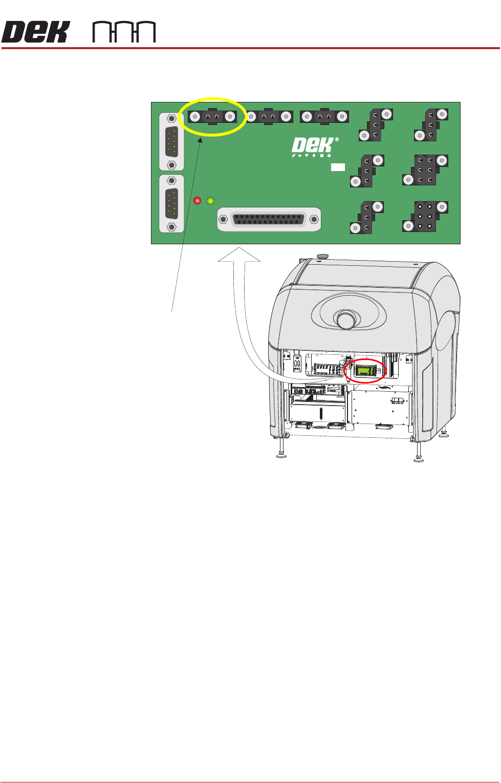
11. Open the rear cover and connect the Grid-Lok connector on N2SK2 - I/O
Node Board 2.
12. Refit the stencil.
13. Power up the machine
14. Setting of the air control regulator must be carried out before running the
machine, Air Control Regulator in the Adjustments and Settings section of
this chapter refers.
View on Rear of Machine
MAIN I/O NODE 2
181436 ISSUE
N2SK2
(Grid-Lok Tooling)
BOARD SUPPORT TOOLING MODULE
REPLACEMENT PROCEDURES
29.16 Technical Reference Manual Chapter Issue 7, Jan 15
Removing Grid-
Lok Tooling
WARNING
BOARD CLAMPS. EXTREME CARE MUST BE EXERCISED WHEN WORKING IN
THE TOOLING AREA OF THE MACHINE TO AVOID INJURY. THE FOILS ON THE
FRONT AND REAR BOARD CLAMPS ARE VERY SHARP.
WARNING
COMPRESSED AIR. COMPRESSED AIR SHOULD NEVER IMPINGE UPON THE
BODY. PORTS, PIPES, ETC MUST NEVER BE BLOCKED BY HAND. BEFORE
CONNECTING OR DISCONNECTING ANY PNEUMATIC COMPONENTS, ENSURE
THE COMPRESSED AIR SUPPLY HAS BEEN DISSIPATED AND DISCONNECTED
FROM THE MACHINE.
1. Select Open Cover Commands.
2. Select Carriage To Rear.
3. Select Shut Down and switch the mains isolator to OFF.
4. Open the front printhead cover.
5. Remove the stencil from the machine.
6. Disconnect and remove the 4mm pneumatic pipes from the manifold to the
tooling modules.
7. Disconnect the two 6mm pneumatic pipes to the manifold.
8. Remove the manifold and the tooling modules from the manual tooling plate.
NOTE
Ensure that the two 6mm pneumatic pipes remain flat on the tooling plate
and do not impinge on the movement of the rear rail or the stencil (when the
rising table is at print height).
9. If vacuum tooling is to be used, open the rear cover and change the
Grid-Lok connector to the vacuum tooling connector on N2SK2 - I/O Node
Board.
PASTE ROLL HEIGHT MONITOR
SAFETY INFORMATION
Chapter Issue 3, Aug 14 Technical Reference Manual 30.1
CHAPTER 30 PASTE ROLL HEIGHT MONITOR
SAFETY INFORMATION
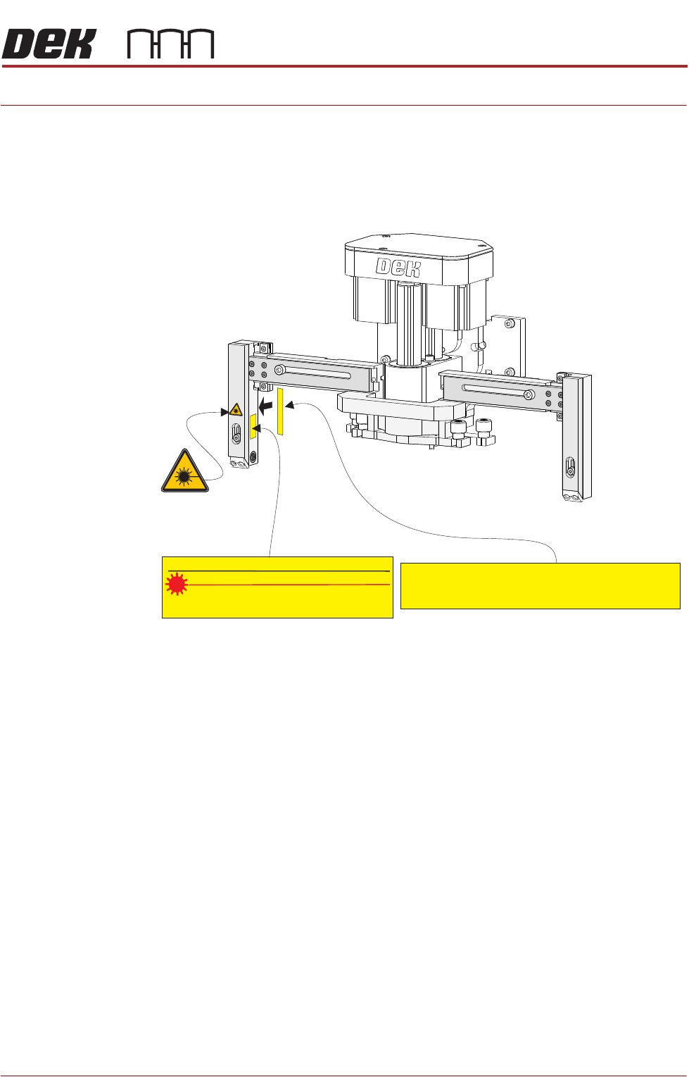
The Paste Roll Height Monitor uses a class 2 laser to detect the height of the
paste roll.
Warning and
Caution labels
Warning labels are located on the sender leg (lhs) as shown:
The labels include:
• The safety warning label; radiation (Laser light source present)
• The manufacturer’s label; date and place of manufacture and the applica-
ble safety standard
• Caution notice; specific safety instruction - do not stare into light source
Manufacturer: DEK, 11 Albany Road, Weymouth, Dorset, DT4 9TH
Country of Manufacture: Germany
Complies with 21CFR1040 with deviations pursuant to Laser Notice 50
Manufacture Date: Month: Year:
DIODE LASER, MAX OUTPUT 1mW
CLASS II LASER, WAVELENGTH 635 +/- 10Nm
FDA Regulation “21 CFR Parts 1040.10 and 1040.11"
Caution Notice
Manufacturer’s Label
Safety
Warning
Label
CAUTION
LASER RADIATION,DO NOT STARE INTO BEAM