192277 - Micron Technical Reference Volume 3.pdf - 第76页
CAMERA SYSTEM MODULE CALIBRATIONS AND CHECKS 23.34 Technical Reference Manual Chapter Issue 9, Feb 18 40. Select Exit . 41. Select Scrn Fid Setup and carry out Fiducial Setup pro cedure as described in Appendix A - V isi…

CAMERA SYSTEM MODULE
CALIBRATIONS AND CHECKS
Chapter Issue 9, Feb 18 Technical Reference Manual 23.33
8. Select Carriage to Rear.
9. Select Unload Screen.
10. Open the front printhead cover.
11. Remove the stencil.
12. Equally space 25 tooling pins on the table.
13. Fit the calibration stencil.
14. Close the front printhead cover.
15. Press the System button.
16. Select Load Screen.
17. Select Back.
18. Select Maintenance.
19. Select Calibrations.
20. Select Offset.
21. Select Setup OK.
22. Place the calibration board with the fiducials downward facing onto the
upline conveyor.
23. Select Auto Board, the board moves to the board stop position.
24. Select Step, the board is clamped and the board stop retracts.
25. Select Step, the camera moves to the first stencil fiducial and the squeegee
moves to dwell height.
26. Using the Incr. and Decr. buttons, position the stencil fiducial (right hand
image) so that it is placed centrally with the box displayed.
27. Select Step, the camera moves to the second stencil fiducial. Position the
fiducial centrally with the box as previously described.
28. Select Step, the camera moves to the third stencil fiducial. Position the
fiducial centrally with the box as previously described.
29. Select Step, the camera returns to the home position and the rising table
moves to the print height position.
30. Select Step, the print carriage moves to the rear position.
31. Open the front printhead cover.
32. Apply paste to all 25 positions on the stencil.
33. Close the front printhead cover.
34. Press the System button.
35. Select Step.
36. Select Step.
37. Select Accept, the table drops and the camera moves to the first fiducial.
38. Select Brd Fid Setup and carry out Fiducial Setup procedure as described
in Appendix A - Vision System Set Up.
39. If any changes have been made, select Learn Fiducial. If no changes have
been made, select Locate Fiducial.

CAMERA SYSTEM MODULE
CALIBRATIONS AND CHECKS
23.34 Technical Reference Manual Chapter Issue 9, Feb 18
40. Select Exit.
41. Select Scrn Fid Setup and carry out Fiducial Setup procedure as described
in Appendix A - Vision System Set Up.
42. If any changes have been made, select Learn Fiducial. If no changes have
been made, select Locate Fiducial.
43. Select Exit.
44. Select Step, the Offset results are displayed.
45. Select Single, the camera moves to each of the 24 remaining fiducial
positions in turn.
46. Select Auto Board, the board data file is saved.
47. Remove the board from the transport rails.
48. Select Exit.
49. Select Back.
NOTE
ASM recommends that the calibration stencil is cleaned with Isopropyl Alcohol
(IPA) impregnated lint free wipe on completion of the offset calibration.
If for any reason the camera cannot locate the board or stencil fiducial (except
for poor prints), select Fiducial Setup and relearn the fiducial, (refer to Appen-
dix A - Vision System Set Up for details on setting up the fiducial recognition
strategy).
Select Retry, the sequence continues and does not have any detrimental effect
to the calibration.
CAMERA SYSTEM MODULE
CALIBRATIONS AND CHECKS
Chapter Issue 9, Feb 18 Technical Reference Manual 23.35
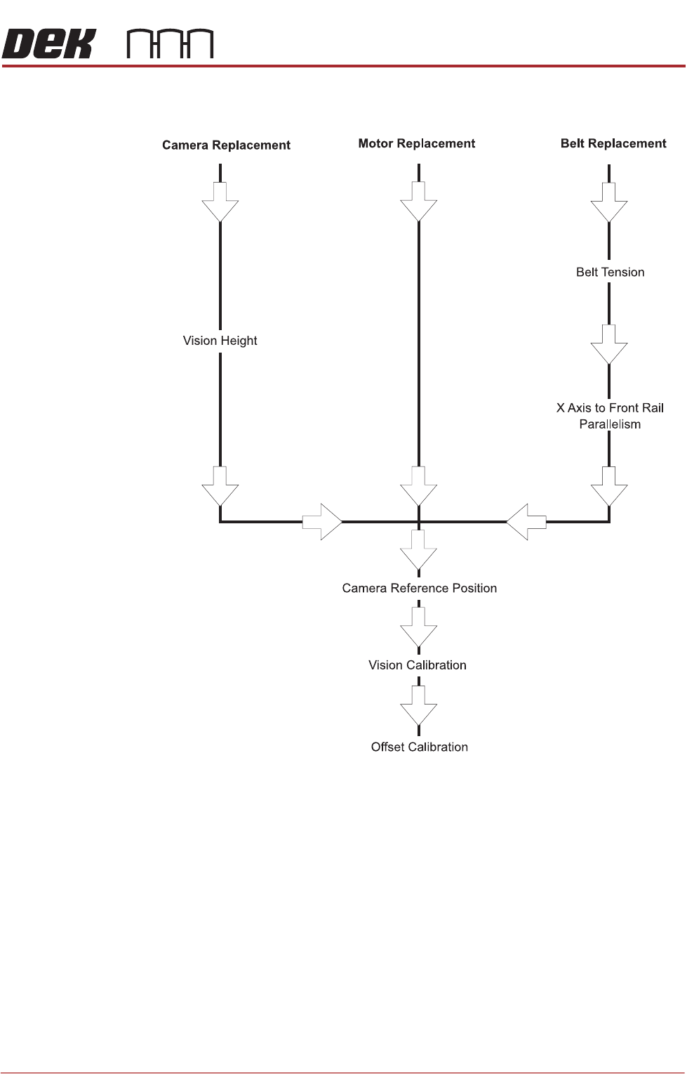
Associated Calibrations
Figure 23-5 Associated Calibrations
NOTE
For information on the Test Cycles function see the Stencil Alignment Chapter.