192277 - Micron Technical Reference Volume 3.pdf - 第176页
PASTE ROLL HEIGHT MONITOR ADJUSTMENTS & SETTINGS 30.8 Technical Reference Manual Chapter Issue 3, Aug 14 17. Select Drive Front Squeegee using Jog Buttons . Press the right hand jog button. Drive the squeegee down un…
PASTE ROLL HEIGHT MONITOR
ADJUSTMENTS & SETTINGS
Chapter Issue 3, Aug 14 Technical Reference Manual 30.7
ADJUSTMENTS & SETTINGS
CAUTION
RADIATION. RISK OF INJURY TO THE EYES DUE TO LASER LIGHT BEING
PRESENT IN THE VICINITY OF THE LABEL. DO NOT LOOK AT THE LIGHT
SOURCE OR REFLECTIONS FROM A SURFACE.
CAUTION
PRINT MEDIUM AND SOLVENTS. WHEN USING OR HANDLING ANY PRINT
MEDIUM OR SOLVENT FORMULATION THE MANUFACTURERS’ SAFETY DATA
SHEETS MUST BE STRICTLY ADHERED TO.
Setup Roll Height
Monitor
To enable the Roll Height Monitor carry out the following:
1. Select Maintenance.
2. Select Machine Setup.
3. Select Options.
4. Change Roll Height Hardware to Fitted.
5. Change Roll Height Monitor to Enabled.
6. Select Back.
7. Select Back.
8. Select Back.
Sensor Height Adjusting the height of the sensor above the tip of squeegee varies the amount
of paste on the stencil prior to an automatic paste replenishment. This can be
set to maintain a paste height of between 10 - 16mm. To adjust the height, carry
out the following:
1. Ensure that a stencil is loaded and that the transport rails and auxiliary
conveyors are free of boards.
2. Select Maintenance.
3. Select Machine Setup.
4. Select Options.
5. Select Roll Height Hardware and set to Enabled.
6. Select Roll Height Monitor and set to Enabled.
7. Select Back.
8. Select Back.
9. Select Diagnostics.
10. Using the Next or Previous buttons; select Print Carriage.
11. Select Home Print Carriage.
12. Select Drive Carriage to Front Position.
13. Select Exit.
14. Using the Next or Previous buttons; select Squeegee.
15. Select Home Front Squeegee.
16. Select Home Rear Squeegee.
PASTE ROLL HEIGHT MONITOR
ADJUSTMENTS & SETTINGS
30.8 Technical Reference Manual Chapter Issue 3, Aug 14
17. Select Drive Front Squeegee using Jog Buttons. Press the right hand jog
button. Drive the squeegee down until the front squeegee is in contact with
the stencil.
18. Select Exit.
19. Open the front printhead cover.
20. Using a 3mm Allen key loosen the paste height adjustment cap headed
screw located on the front of the right hand leg.
21. Adjust the length of the leg to the required sensor height. Tighten the cap
headed screw.
22. Repeat Steps 7 and 8 for the left hand leg.
23. Close the front printhead cover.
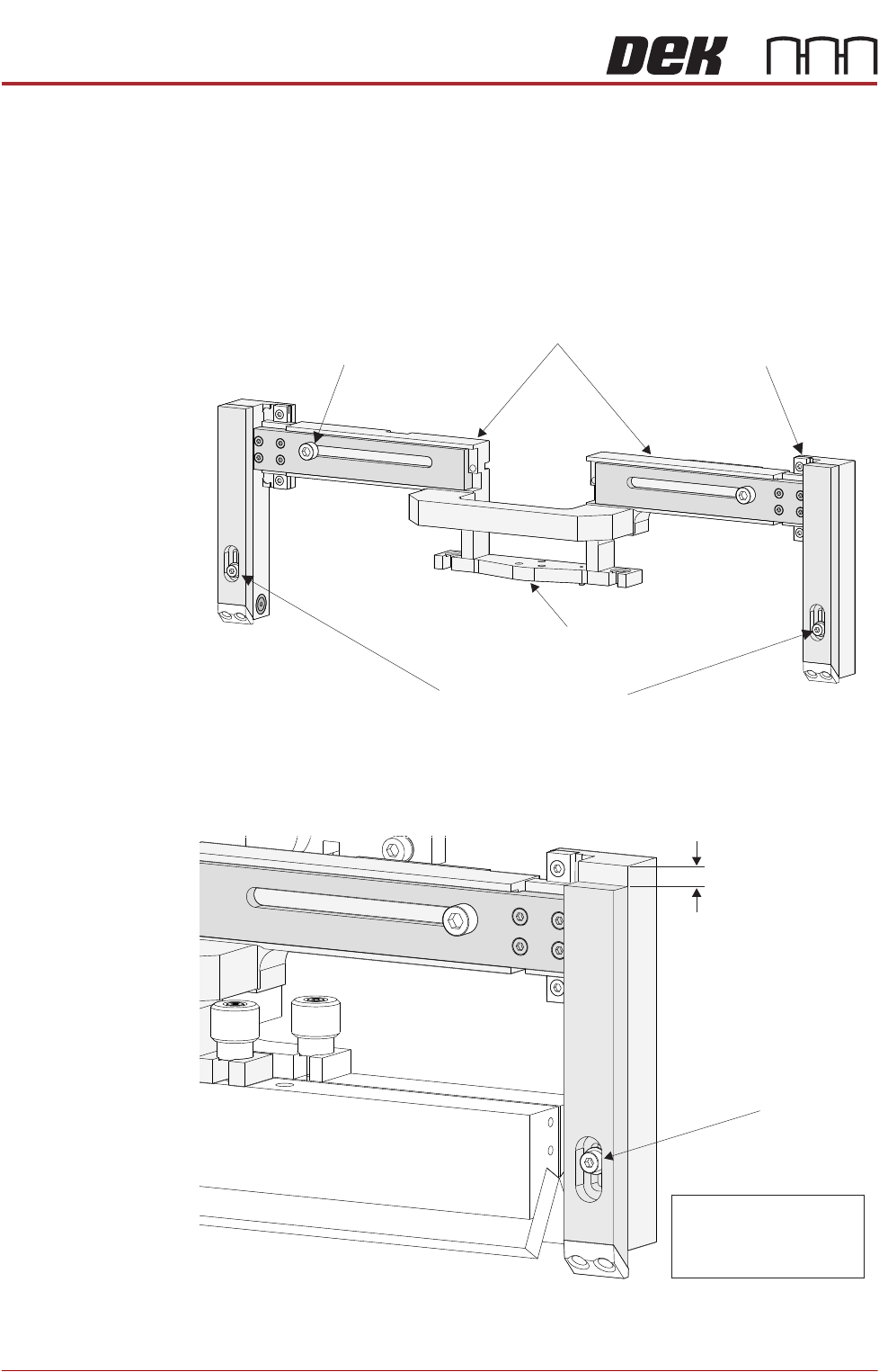
Paste Height Adjustment
Securing Screw
(in 2 positions)
THK Linear Bearing
(in 2 positions)
Width Adjustment Securing Screw
(in 2 positions)
Front Squeegee
Mount
Horizontal Beam
Paste Height
Adjustment
(0 - 10mm)
NOTE
Paste Height =
Paste Height Adjustment
+ 10mm
Paste Height Adjustment
Locking Screw
PASTE ROLL HEIGHT MONITOR
ADJUSTMENTS & SETTINGS
Chapter Issue 3, Aug 14 Technical Reference Manual 30.9
24. Press the System button.
25. Select Exit.
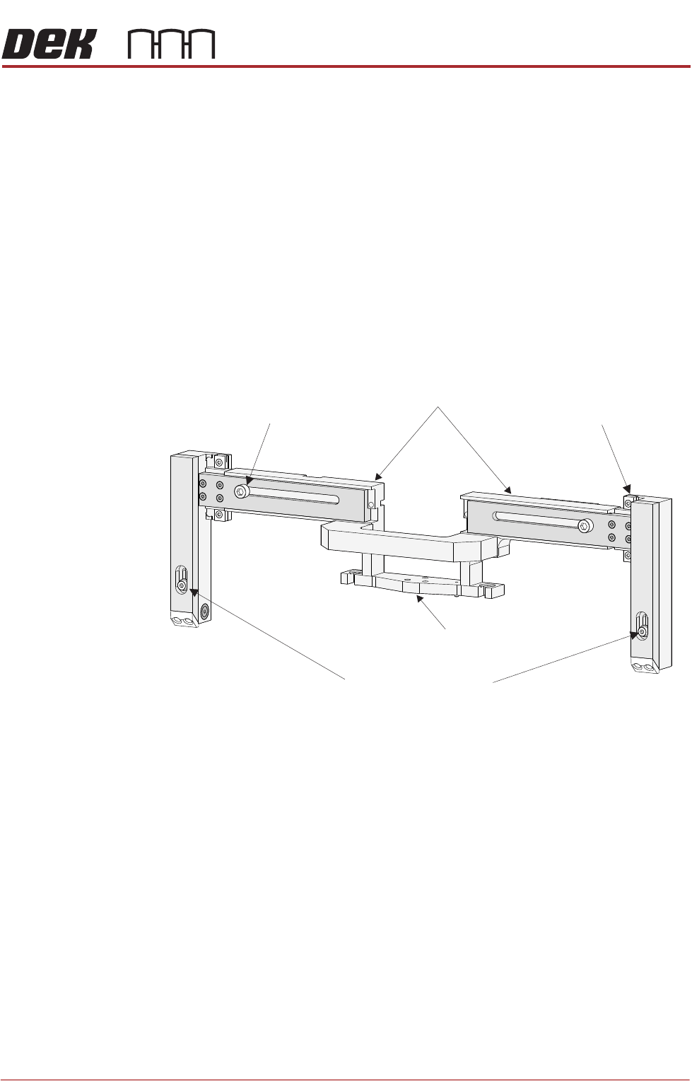
Beam Width
Adjustment
The width of the beam is set to accommodate the front squeegee and the
product.
1. Select Diagnostics.
2. Using the Next or Previous buttons; select Print Carriage.
3. Select Home Print Carriage.
4. Select Drive Carriage to Front Position.
5. Select Exit.
6. Open the printhead front cover.
7. The beam width adjustment screws are located as shown below.
Paste Height Adjustment
Securing Screw
(in 2 positions)
THK Linear Bearing
(in 2 positions)
Width Adjustment Securing Screw
(in 2 positions)
Front Squeegee
Mount
Horizontal Beam