M8_ServiceManual_e.pdf - 第21页
1 Installation 1-7 Lever NOTE: The height must be 890 t o 920mm in the case of C FB wagon spec. NOTE: The adjust feet must be turned using a M30 single-head wrench (nom inal: 46mm). ⑤ Place a leveler on the base of the m…
1 Installation
1-6
ACTION:
① Locate the machine to the specified place.
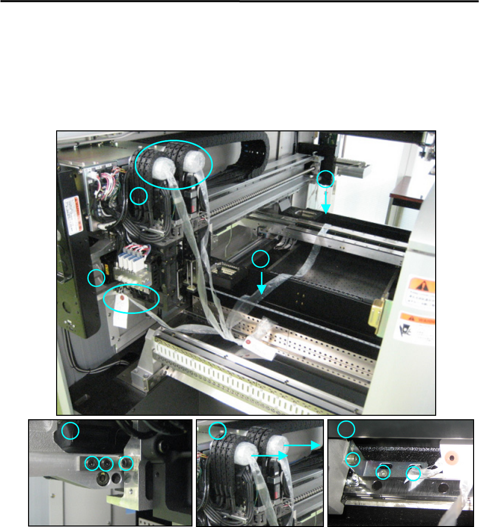
② Remove metal fittings that fasten Head Unit, X and Y Beams, in order to prevent to move during
transportation, and also detach cushions put in the head cable bear. After that, check to see that the X
beams and heads can move to the Y direction manually.
③ Five ropes can be taken off if five points have been removed.
Note; Please keep the metal fittings, they will be needed when moving the machine.
④ When the machine is installed stand alone, turn the adjust feet so that the PCB transfer height is the
same as the conveyor height (900±20mm (see Note)) of the reference equipment. In the case of
SMEMA interface spec, the height must be 950±20mm.
④ When the machine is connected to the Pre-process on production line, adjust the PCB transfer height
to the conveyor rail height of the Pre-process.
)
Production Line
出荷時の内部写真(背面側)
X 軸 Y 軸 ヘッド
A
C
B
B
A
C
C
1 Installation
1-7
Lever
NOTE: The height must be 890 to 920mm in the case of CFB wagon spec.
NOTE: The adjust feet must be turned using a M30 single-head wrench (nominal: 46mm).
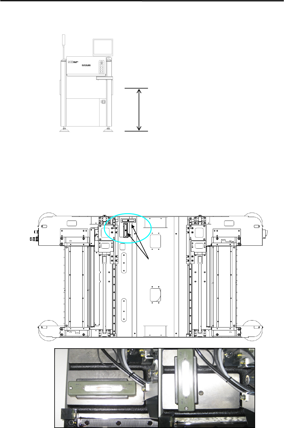
⑤ Place a leveler on the base of the machine. Set the position to the conveyor of the Pre-process finely
until the machine is leveled.
) Supplementary Explanation for Installation
900±20mm
Or
950±20mm (SMEMA)
Front
1 Installation
1-8
⑥ After the machine is positioned, make sure that a board runs smoothly between upstream and
downstream conveyors.
⑦ Place a leveler on the Y beam and make a fine adjustment so that the difference in leveler when the Y
beam moves rightward and leftward will be within 1 scale (1 scale is 0.02mm/m). (To prevent a Y
beam distortion.)
⑧ Lock the adjust foot nuts lastly.
NOTE: The adjust foot nuts must be locked with a closed wrench (nominal: 46mm) or a single-head wrench.
⑨ Connect the power cable and ground line independently of other machines which may be a noise
source, such as a compressor, welding machine.
⑩ Connect an intake-side air coupler 65SN or 85SN (Nitto Kohki) or equivalent to the air regulator
coupler located on the rear of the machine. After the coupler is connected, make sure that the air
regulator’s reading is 0.45MPa
Lever
Put the lever at the middle of
Y Beam.