M8_ServiceManual_e.pdf - 第27页
1 Installation 1-13 Removal of Rust Inhibiting Grease At packing and shipping, a large amount of grease is applied on the surface of each ball-screw and linear guides on Y-axis in order to prevent rust. As each axis move…
1 Installation
1-12
Put cable clamps on screw holes, and
fasten the power cable with cable ties.
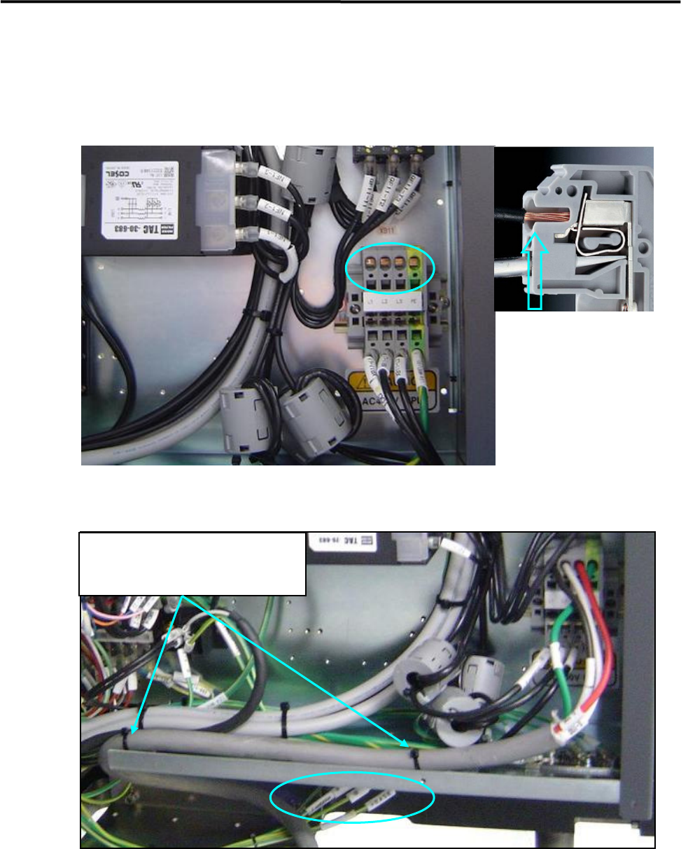
Power Cable Wiring
Route the power cable to outside the mounter through the rectangle cable at the lower part of the rear cover
(see Fig 1 and 2).
In the above picture, circle holes are insertions of power cables and square holes are insertions of tools. At
first, insert a driver to the square hole and press down the driver, insert a power cable to the circle hole, and
pull the driver out, then the cable will be clamped.
The power cable should be secured inside the mounter to prevent accident disconnection by pulling on the
cable outside the mounter.
To fasten the power cable with cable ties, first attach cable clamp to unused screw holes then insert cable
ties through the cable clamps. Or bind the power cable to the terminal-panel leg with cable ties.
・Recommended Driver
4mm minus Driver
・Recommended Cable
3.5 ㎟ / Withstand Voltage 600V
・Length of peeling off cables
12mm
1 Installation
1-13
Removal of Rust Inhibiting Grease
At packing and shipping, a large amount of grease is applied on the surface of each ball-screw and linear
guides on Y-axis in order to prevent rust. As each axis moves an excess grease is gradually removed from
their surface and a proper amount of grease remains as a lubricant.
For this reason, when these axes are moved at installation, the extra grease may be built up on ball-screw
nuts, on linear guide sliders, and both ends of each axis. If you run the machine at high speed (production)
without wiping it away, the grease may be scattered around due to centrifugal force and vibration, and that
may stick to cameras, sensors, or a board.
Please perform a warm-up at low speed once the origin is acquired after installation, and wipe off any
excess grease as necessary.
The mounter may not function properly when grease sticks to the sensors
and the cameras.
ACTION:
① Check and remove any board and tools from inside of the mounter, and then perform origin
acquisition.
② Select Main Menu> Manual> Warm Up.
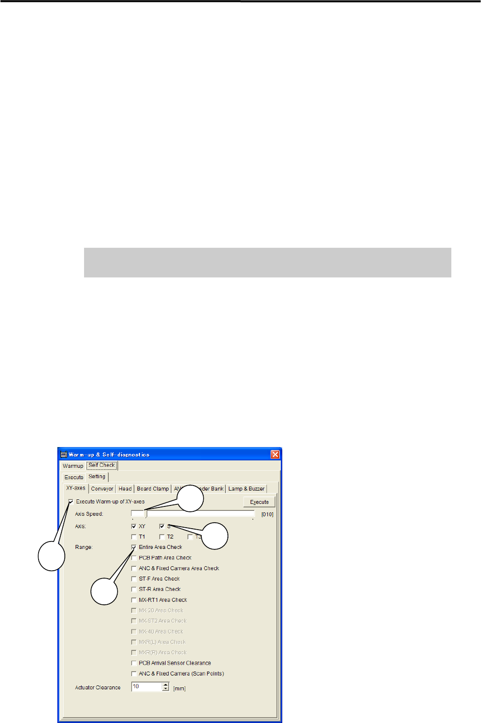
③ Select Warm-up & Self-diagnostics> Setting.
④ Select [XY-axes] and set up the parameters as follows.
***** This function is not ready for now. *****
1: Have a check mark on
“Execute Warm-up of XY-axes”.
2: Move the scroll bar and set
“Axis Speed” at 10%.
3: Have a check mark on XY and S
under “Axis”.
4: Have a check mark on
“Entire Area Check“ under “Range”.
NOTE: It is not necessary to have
check marks on the other parameters.
3
1
2
4
1 Installation
1-14
⑤ Disable all the parameters in other tab fields than [XY-axes]. Remove a check mark on each
parameters in [Conveyer], [Head], [Board Clamp], [ANS], [Feeder Bank], and [Lamp & Buzzer] (tabs
may vary due to mounter’s option settings.) in order to carry out only the selected parameters in
[XY-axes].
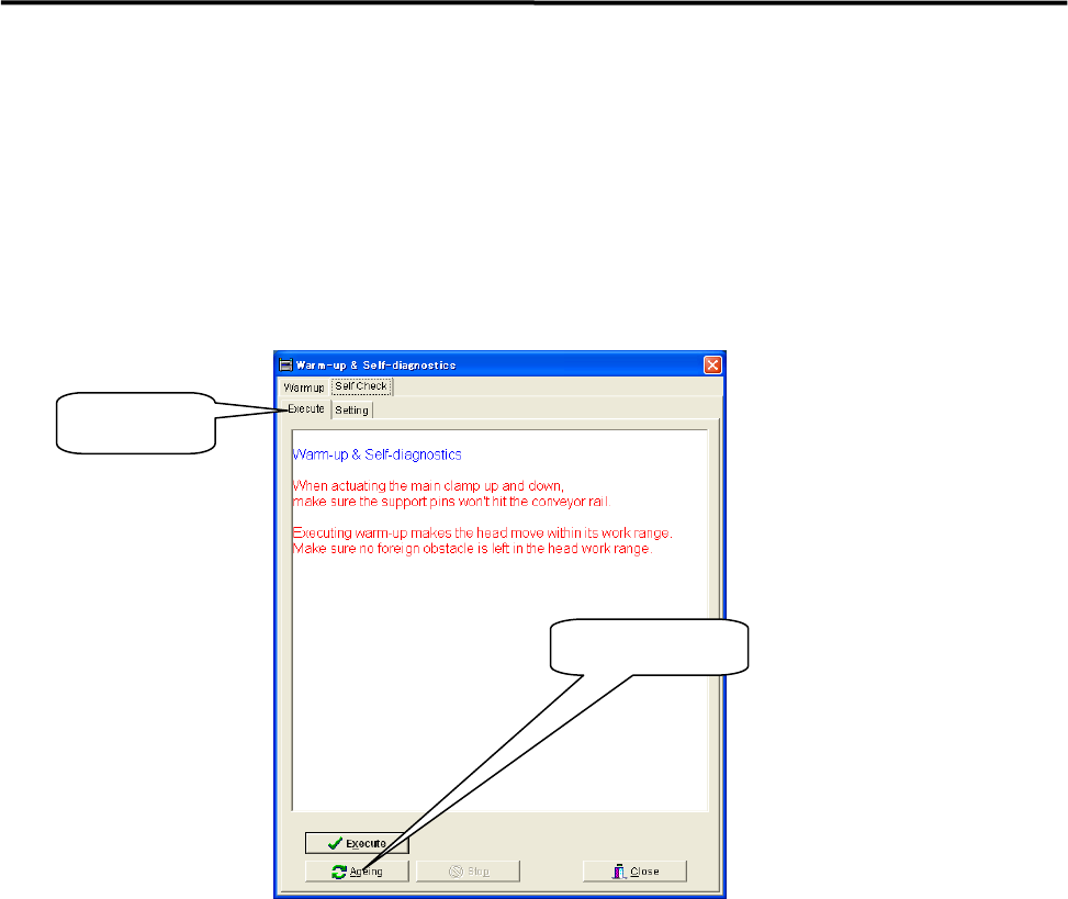
⑥ Select [Execute] and click <Ageing>.
When [Execute] tab is selected, the <Execute> button and the<Ageing> button are found at the
bottom of the window. Clicking the <Execute> button enables to perform warm-up only a single
cycle and sufficient ageing is not carried out.
⑦ Continue ageing for 5 to 10 minutes.
After 5 to 10 minutes, click the <Stop> button to stop ageing.
⑧ Wipe off excess grease.
Use a unwoven cloth to wipe off excess grease which is built up on ball-screw nuts, on linear guide
sliders, and both ends of each axis.
NOTE: Refer to Chapter 3 Mechanical Section for the location of each axis.
⑨ Check to be sure that the excess grease has not been scattered around.
Make sure the excess grease has not been stuck on sensors, cameras, conveyer and its belts, and ANC
When it has been stuck on these parts, remove it with unwoven cloth.
NOTE: Refer to Chapter 3 mechanical Section for more detail in cleaning of scan camera and mirror.
Ageing Button
Execute Tab