M8_ServiceManual_e.pdf - 第28页
1 Installation 1-14 ⑤ Disable all the parameters in other tab fields than [XY-axes]. Rem ove a check mark on each parameters in [Conveyer], [Head], [Board Clamp], [ANS], [Feeder Bank], and [Lam p & Buzzer] (tabs may …
1 Installation
1-13
Removal of Rust Inhibiting Grease
At packing and shipping, a large amount of grease is applied on the surface of each ball-screw and linear
guides on Y-axis in order to prevent rust. As each axis moves an excess grease is gradually removed from
their surface and a proper amount of grease remains as a lubricant.
For this reason, when these axes are moved at installation, the extra grease may be built up on ball-screw
nuts, on linear guide sliders, and both ends of each axis. If you run the machine at high speed (production)
without wiping it away, the grease may be scattered around due to centrifugal force and vibration, and that
may stick to cameras, sensors, or a board.
Please perform a warm-up at low speed once the origin is acquired after installation, and wipe off any
excess grease as necessary.
The mounter may not function properly when grease sticks to the sensors
and the cameras.
ACTION:
① Check and remove any board and tools from inside of the mounter, and then perform origin
acquisition.
② Select Main Menu> Manual> Warm Up.
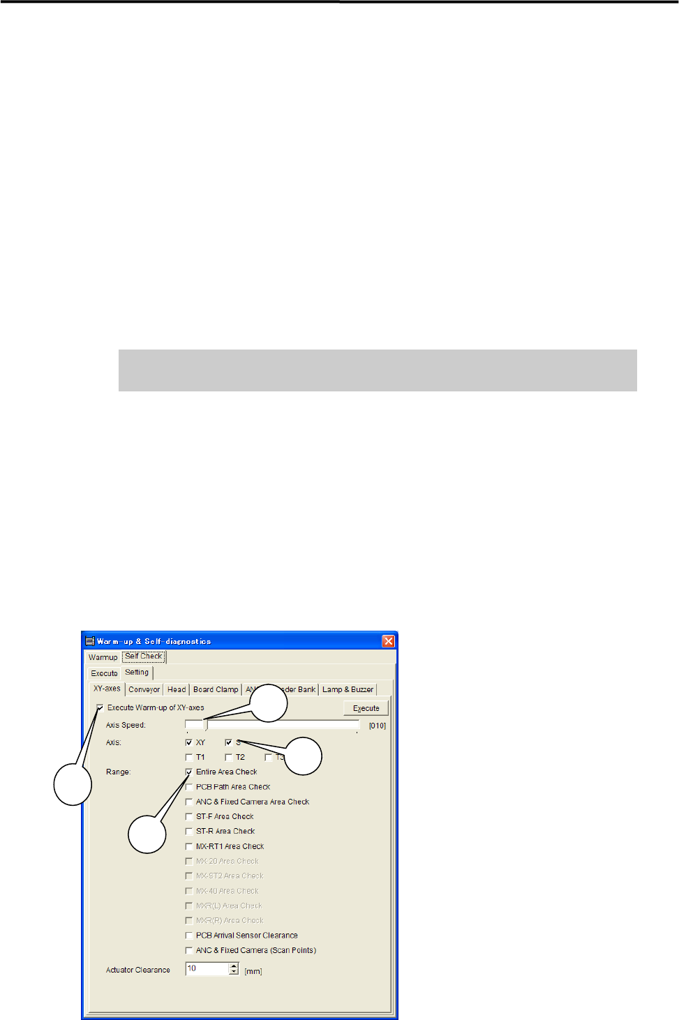
③ Select Warm-up & Self-diagnostics> Setting.
④ Select [XY-axes] and set up the parameters as follows.
***** This function is not ready for now. *****
1: Have a check mark on
“Execute Warm-up of XY-axes”.
2: Move the scroll bar and set
“Axis Speed” at 10%.
3: Have a check mark on XY and S
under “Axis”.
4: Have a check mark on
“Entire Area Check“ under “Range”.
NOTE: It is not necessary to have
check marks on the other parameters.
3
1
2
4
1 Installation
1-14
⑤ Disable all the parameters in other tab fields than [XY-axes]. Remove a check mark on each
parameters in [Conveyer], [Head], [Board Clamp], [ANS], [Feeder Bank], and [Lamp & Buzzer] (tabs
may vary due to mounter’s option settings.) in order to carry out only the selected parameters in
[XY-axes].
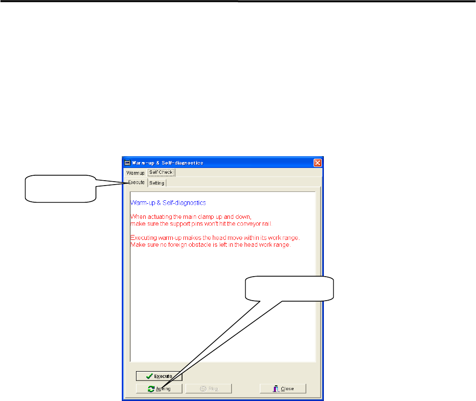
⑥ Select [Execute] and click <Ageing>.
When [Execute] tab is selected, the <Execute> button and the<Ageing> button are found at the
bottom of the window. Clicking the <Execute> button enables to perform warm-up only a single
cycle and sufficient ageing is not carried out.
⑦ Continue ageing for 5 to 10 minutes.
After 5 to 10 minutes, click the <Stop> button to stop ageing.
⑧ Wipe off excess grease.
Use a unwoven cloth to wipe off excess grease which is built up on ball-screw nuts, on linear guide
sliders, and both ends of each axis.
NOTE: Refer to Chapter 3 Mechanical Section for the location of each axis.
⑨ Check to be sure that the excess grease has not been scattered around.
Make sure the excess grease has not been stuck on sensors, cameras, conveyer and its belts, and ANC
When it has been stuck on these parts, remove it with unwoven cloth.
NOTE: Refer to Chapter 3 mechanical Section for more detail in cleaning of scan camera and mirror.
Ageing Button
Execute Tab
1 Installation
1-15
Pre-Process and Post-Process of Machine
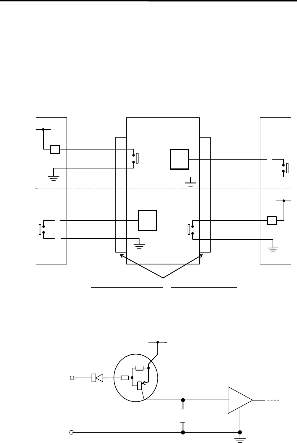
Connecting Pre-Process and Post-Process
When using other manufacturer’s machines as the pre-process or post-process, connect them as shown in
the below diagram. No-voltage output (relay) is recommended for post-process.
Standard spec. : Upper half of the diagram.
SMEMA Interface spec. : Whole diagram.
*INPUT
CIRCUIT
*INPUT
CIRCUIT
2
1
CN2 CN1
Post-process
Connector (Cable side)
AMP
206044-1(plug)
66099-2 or equivalent (pin)
206070-1(cable clamp)
Connector (Mounter side)
AMP
206043-1(receptacle)
Mounter Pre-process
BOARD
AVAILABLE
BOARD
AVAILABLE
MACHINE
NOT READY
4.7KΩ
4.7KΩ
Input
terminal
*INPUT CIRCUIT
+5V
30VDC 1A or less
100VAC 0.5A or less
RELAY
RELAY
MACHINE
NOT READY
3
4
2
1
3
4
COM