M8_ServiceManual_e.pdf - 第61页
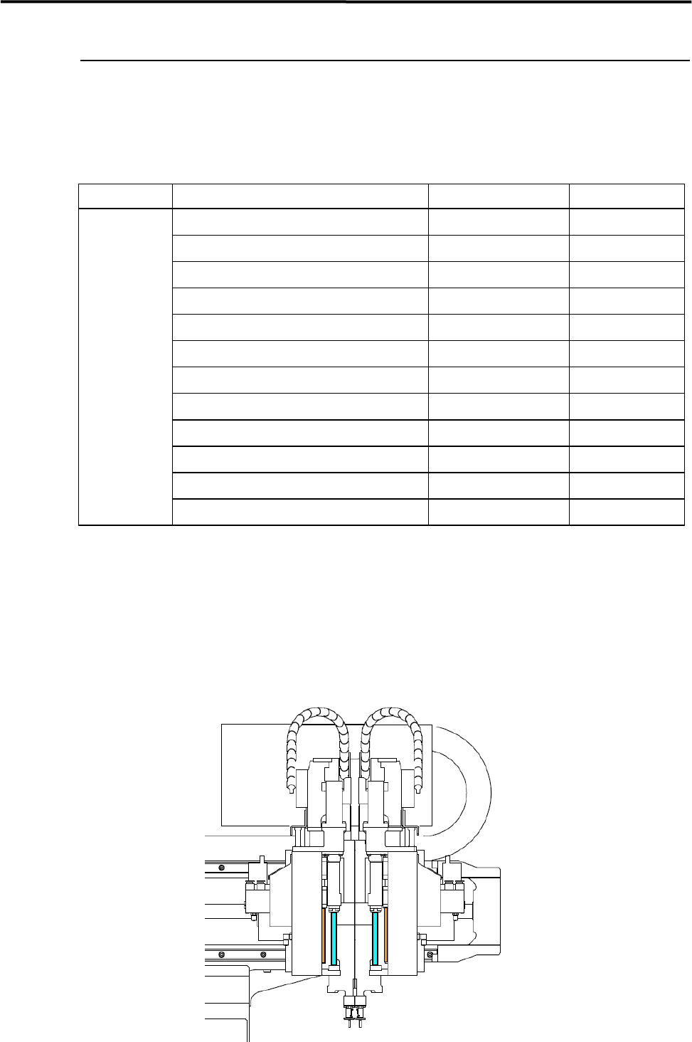
3 Mechanical Section 3-21 ■ Lubrication Poin ts for X/Y M8 Slider Ball Screw X Axis Slider, Ball Screw Y Axis Slider, Ball Screw
3 Mechanical Section
3-20
Lubrication
Lubrication Points
Lubricate the specified portions listed below with cotton swab soaked with lubricant.
UNIT PORTION LUBRICANT FREQ.
Ball Screw of X-axis Grease Every two weeks
Linear Guide of X-axis (Upper and Lower) Grease Every two weeks
Ball Screw of Y-axis (Right and Left) Grease Every two weeks
Linear Guide of Y-axis (Right and Left) Grease Every two weeks
Feeder Bank Plates Grease Every two weeks
Conveyor Width Adjusting Screw Grease Monthly
M8 Conveyor Guide Shaft Grease Monthly
Ball Screw of Z-axis Grease Every two weeks
Spline Shaft of Z-axis Grease Every two weeks
Linear Way of Z-axis Grease Every two weeks
Nozzle Holder Silicone Grease Monthly
Nozzle Silicone Grease Weekly
NOTE: Do not apply excessive oil/grease. This may cause oil/grease scattering when the mounter is in operation.
■ Z Axis Ball Screw, Z Axis Linear Guide
① Wipe off grease fixed on the ball screw and linear guide. Please use nonwoven cloth that lint does not
remain.
③ Apply new grease on the ball screw and linear guide by finger. Please do not apply grease partially,
but overall and uniformly.
3 Mechanical Section
3-21
■ Lubrication Points for X/Y
M8
Slider
Ball Screw
X Axis Slider, Ball Screw
Y Axis Slider, Ball Screw
3 Mechanical Section
3-22
Lubrication
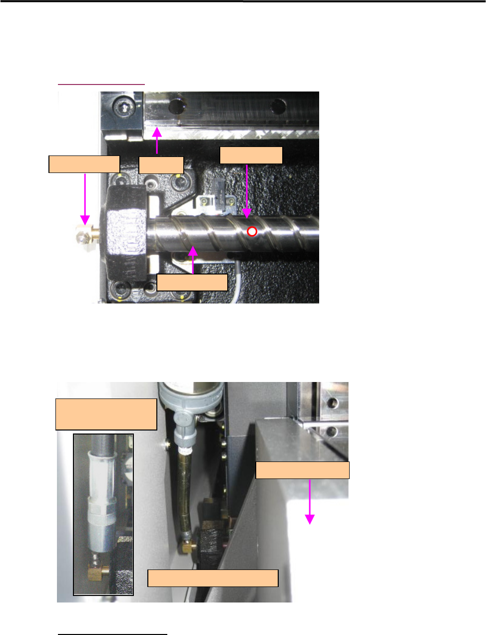
X Axis Ball Scew
Grease Injection
Grease Injection Method
① Move the head assembly to the middle of the axis.
② Move the Y Axis Beam Unit to the left side of the machine.
③ Attach the grease gun to the grease nipple as shown in the above picture.
④ Inject grease into the ball screw.
・
The grease will be injected from the grease slot through the grease nipple.
・
The beam unit has to be moved to the grease nipple side when injecting grease.
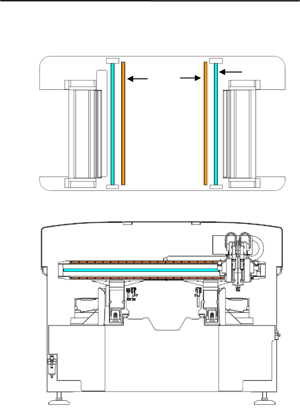
Grease Nipple
Grease Nipple
Grease Slot
Ball Screw
Slider
Grease Gun and Grease Nipple
Y Axis Beam Unit
Recommended Grease Gun
LE4-M86A1-00X