M8_ServiceManual_e.pdf - 第54页
3 Mechanical Section 3-14 ■ Attaching O-ring and Nozzle Filter ACTION: ① Insert the filter with tweezers and adjust the position of the filter using the O-ring insertion jig. Correct Incorrect ② Set the O-ring at the tip…
3 Mechanical Section
3-13
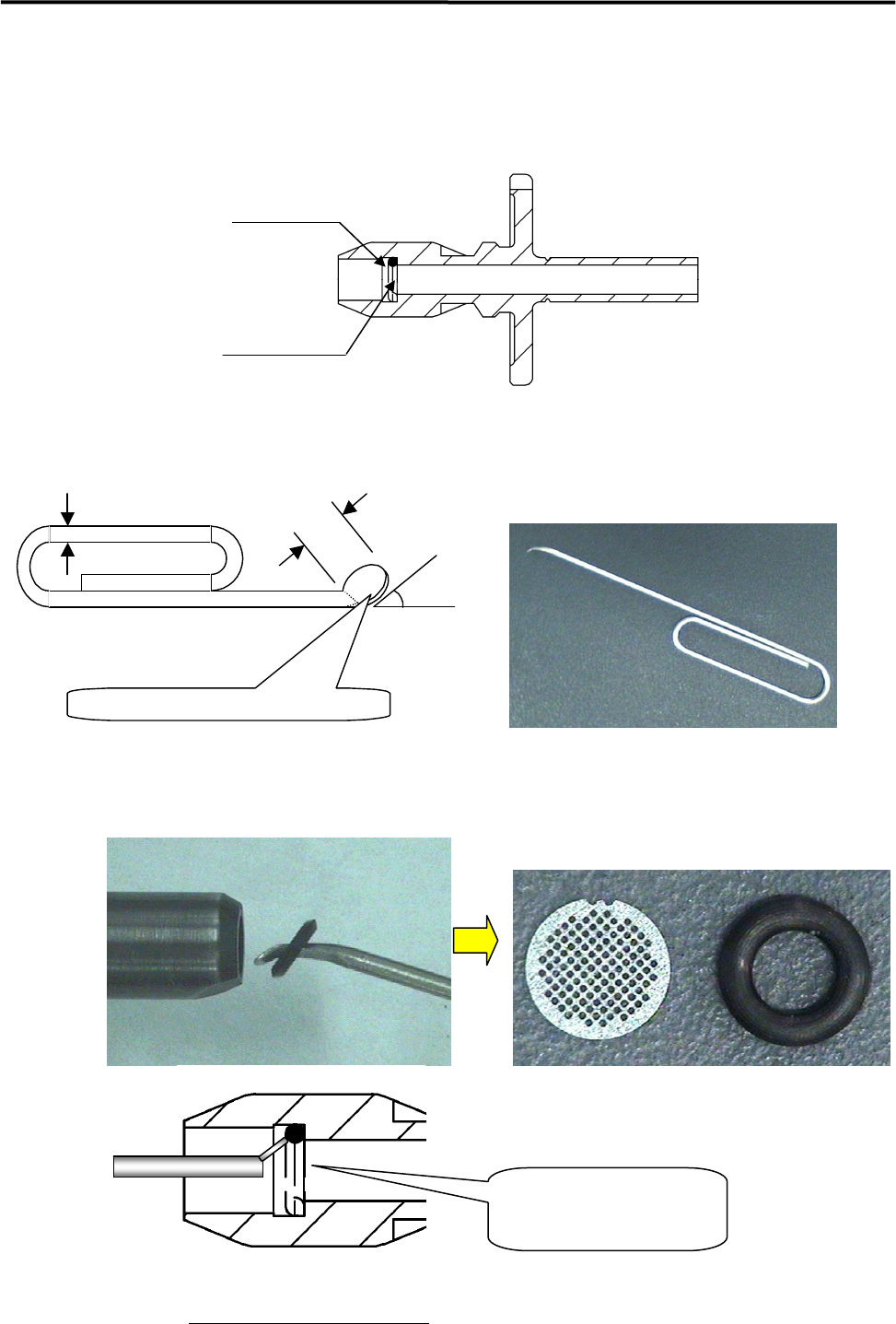
■ Removing O-ring and Nozzle Filter
NOTE: The filter is fixed by the O-ring. It has no right-side up.
① Insert an O-ring removal jig like illustrations below into the nozzle from its rear end.
Jig: Modify a commercially available clip.
Dia.1mm
3mm
30 to 45 degrees
Flatten the pin edge by pliers.
(
t=0.3mm
)
② Insert the pin-edge of the jig between the O-ring and the seating face, and pull it out from the nozzle
(take care not to let the O-ring come off).
Magnified view of O-ring part
Insert the flatten pin-edge between
the O-ring and the seating face.
O-ring
Filter
ACTION:
3 Mechanical Section
3-14
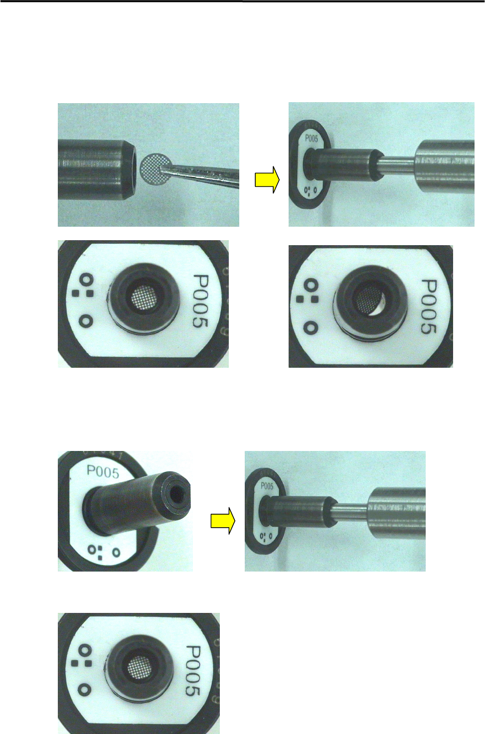
■ Attaching O-ring and Nozzle Filter
ACTION:
① Insert the filter with tweezers and adjust the position of the filter using the O-ring insertion jig.
Correct Incorrect
② Set the O-ring at the tip of the nozzle and push it slowly using the O-ring insertion jig to the bottom of
the nozzle.
③ Remove the jig slowly.
④ Check that the filter and the O-ring have been set in place correctly.
3 Mechanical Section
3-15
Nozzle Recognition Stickers
Labeling a Nozzle ID Sticker to a Nozzle
ACTION:
① From the surface to which the sticker is to be affixed, remove oil, dust and water content completely
using industrial alcohol.
② Pull out the shaft of the nozzle sticker tool approx. 3mm from the ring.
③ Peel the sticker from the paper using tweezers.
④ Place the sticker with its adhesive side up, and then put it in the jig (make sure that the D-cut on the
sticker is aligned with that on the ring). (The sticker must be angled so that the nozzle ID no. is
oriented as illustrated below.) Take care not to touch the adhesive surface with fingers.
⑤ Push the nozzle into the shaft. Make sure that the nozzle’s notch is aligned with the positioning slot on
the ring.
⑥ While pressing the nozzle’s rim, push the shaft into the ring so that the sticker is affixed onto the
nozzle.
⑦ Check that the sticker touches the bottom of the ring.
NOTE: If the shaft is pulled out of the ring too much, it may come off. If it comes off, align the shaft’s slot with the
ring’s positioning pin and then insert the shaft into the ring slowly.
Part Name
Part No. Remark
ID SEAL TOOL, ASSY. LC1-M8903-00X ID sticker tool
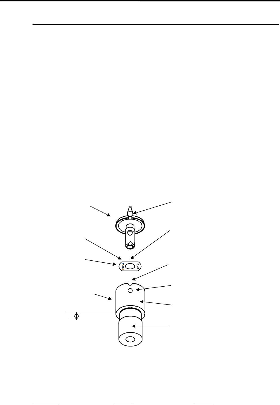
Nozzle ID sticker tool
D-cut
Shaft
Positioning pin
Ring
Positioning slot
Nozzle ID sticker
Nozzle
Notch
ID No. (P***)
3mm