M8_ServiceManual_e.pdf - 第97页
4 Electrical Section 4-29 ⑤ Set up the code setting Press keys at the same time for four seconds. ⑥ Finally, adjust the conveyor width to the m inimum , and then confirm that t he conveyor does not interfere with the sen…
4 Electrical Section
4-28
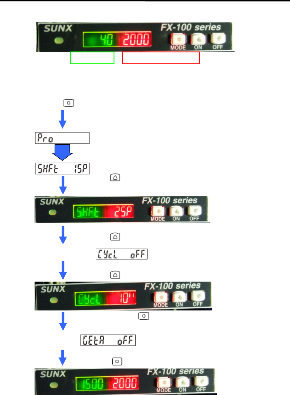
④ Set up the threshold follow-up cycle of the fiber amplifier.
Set “Shift Quantity” to 25% and “Follow-up Cycle” to 10 seconds.
Press key more than 4 seconds in the normal detection condition.
Proceed to “ Pro Mode” and change to threshold follow-up cycle setting automatically.
Press key to show “ 25P” .
Press key two times.
【NOTE】Check that the threshold has been 25% to the received light value.
The threshold will be still low just after setting.
Threshold value Received Optical Light Value
Auto
Current Threshold
Follow-up Cycle Setting
(In case of “OFF” setting)
Press key and set it to “10 seconds”.
Fix the setting by key.
Current GETA
Function Setting
(In case of “OFF” setting)
Press key six times or keep pressing for two seconds.
4 Electrical Section
4-29
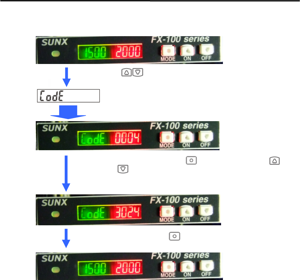
⑤ Set up the code setting
Press keys at the same time for four seconds.
⑥ Finally, adjust the conveyor width to the minimum, and then confirm that the conveyor does not
interfere with the sensor and PCB can be detected when loading PCB.
* The contents of the threshold follow-up cycle setting is .
Auto
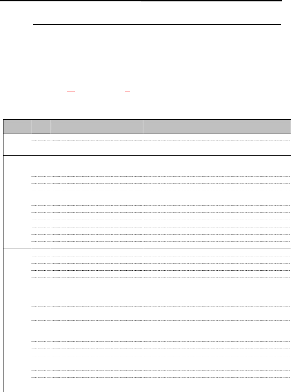
Blink the first digit by pressing key, and then select code by
and key.
Repeat the same operation from second to third digit, then display “3024”.
Fix the code by pressing key.
Confirm that the setting has been changed.
4 Electrical Section
4-30
Motor Troubles
The alarm codes when the motor alarm happened are shown in the below table.
The alarm code in the error message log is shown in the decimal number, but the actual alarm code is
followed by the hexadecimal system, then the code number has to be converted the hexadecimal number in
order to refer to the alarm code list.
Example)
・Error Message ; “Head 1 Y Axis Servo Alarm has been detected. (Alarm Code;113(2) Control Power Short Voltage)
・Alarm Code 113 (Decimal Number) ⇒ 71 (Hexadecimal Number)
Alarm Code List
Type
Alarm
Code
Alarm Name Alarm Meaning
01H Serial Communication Abnormal 1
・Not receive normal frame 4 times in row.
02H Serial Communication Abnormal 2
・Not receive synchronous frame 4 times in row.
Communi
cation
Error
03H Serial Communication Abnormal 3
・Receives synchronous frame at different time from update time.
21H Power Element Error (Over Current)
・Overcorrect of driving module
・Driving power error
・Driving module overheating
22H Current Detection Error 0
・Current detect value error
23H Current Detection Abnormal 1
・Current detect circuit error
Driving
System
Error
24H Current Detection Abnormal 2
・Communication error with current detect circuit
41H Overload 1
・Excessive effective torque
42H Overload 2
・Stall overload
43H Regeneration Error
・Excessive regenerative load ratio
51H Amplifier Overheating
・Overheat detection of AMP ambient temperature
52H In-rush prevention resistor overheating
・Detects overheating of in-rush prevention resistor
53H DB Resistor Overheating
・Overheat detect of DB resistor
Load
Error
54H Internal Overheating
・Excessive DC voltage of main circuit
61H Overvoltage
・Excessive DC voltage of main circuit
62H Main Circuit Short Voltage
・DC voltage failure of main circuit
63H Main Power Failed Phase
・One phase disconnection of 3 phase main circuit power
71H Control Power Short Voltage
・Voltage failure of control power
Power
Error
72H +12V power loss
・+12V power loss
81H Pulse Signal Error 1 of Encoder Phase A, B
・Signal line disconnection (A,B,Z) of incremental encoder
・Disconnection of power line
82H Absolute Signal Disconnected
・Signal line disconnection (PS) of absolute encoder
84H
Communication Error between Encoder
and Amplifier
・Encoder serial signal time out
85H Encoder Initialization Error
・Read failure of incremental encoder CS data
・Initialization error of absolute encoder
・Cable disconnection
87H CS Wire Disconnected
・CS signal line disconnection
91H Encoder Command Error
・Mismatch of send command and receive command
92H Encoder FORM Error
・Start/Stop bit error
・Shortage of data length
93H Encoder SYNC Error
・Cannot receive data within specified time after command is sent.
Encoder
Wiring
Error
94H Encoder CRC Error
・Mismatch of CRCs generated form the received data and has been
sent