M8_ServiceManual_e.pdf - 第24页
1 Installation 1-10 Supplementary Explanation for Installation When setting up a production line, level adjustment a nd line positioning of the machine m ay be carried out at the same time. However, to fine-adjust the ma…
1 Installation
1-9
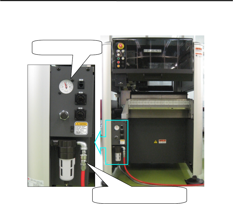
Air Regulator
Instruction Pressure; 0.45MPa
Intake-side air coupler
65SN/85SN (Nitto Kohki) or equivalent
1 Installation
1-10
Supplementary Explanation for Installation
When setting up a production line, level adjustment and line positioning of the machine may be carried out
at the same time. However, to fine-adjust the machine position with the machine level, i-PULSE
recommends that the machine be roughly positioned to the production line first, and then be leveled and
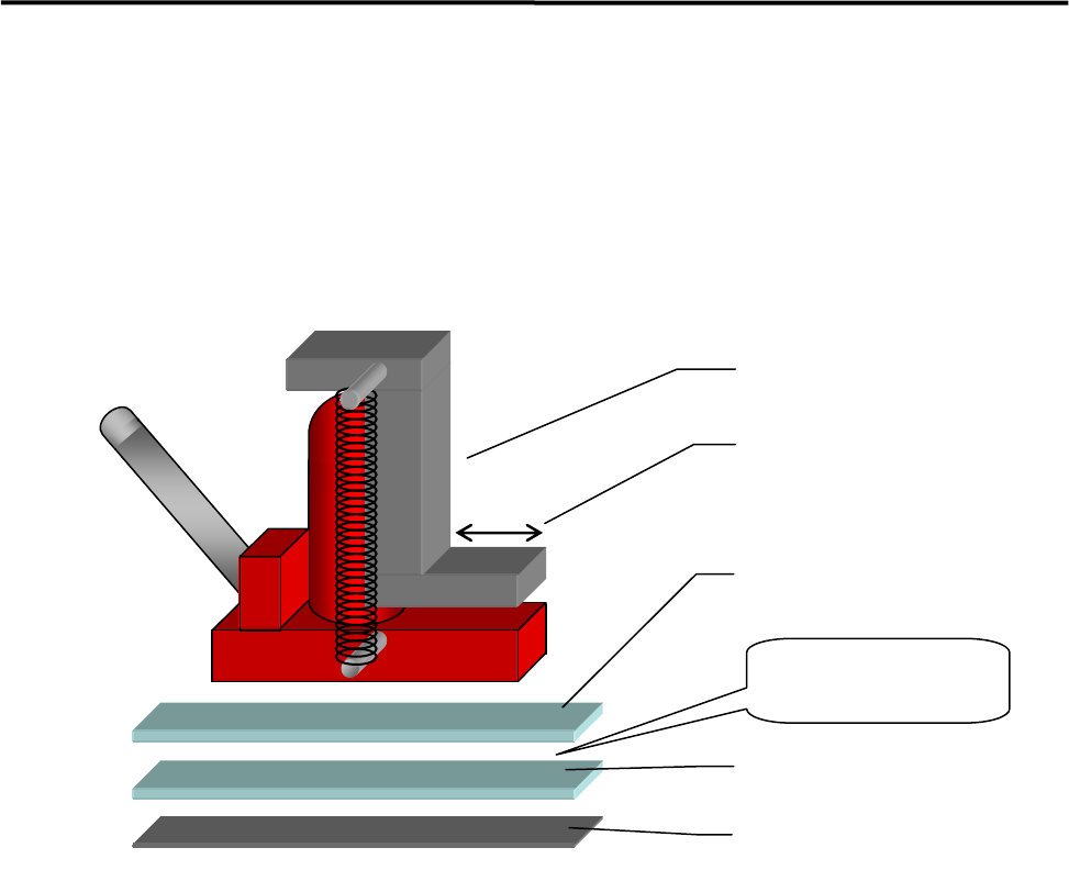
positioned accurately using the following four sets comprising a hydraulic jack and plates.
ACTION:
① Bond the non-slip base rubber with base plate 2.
② Apply grease between base plates 1 and 2 for lubrication purposes.
③ Place a plate set near each machine jack-up point (four points).
④ Place a jack on each plate set and jack up the machine.
⑤ Adjust each jack so that the machine is level.
⑥ Fine-adjust the position of the machine while the machine is jacked up. (The machine can be moved
lengthwise and crosswise with help of grease applied between the plates.)
Hydraulic jack
Base plate 1
Base plate 2
Base rubber
Apply grease
between the
p
lates.
Hook stroke
1 Installation
1-11
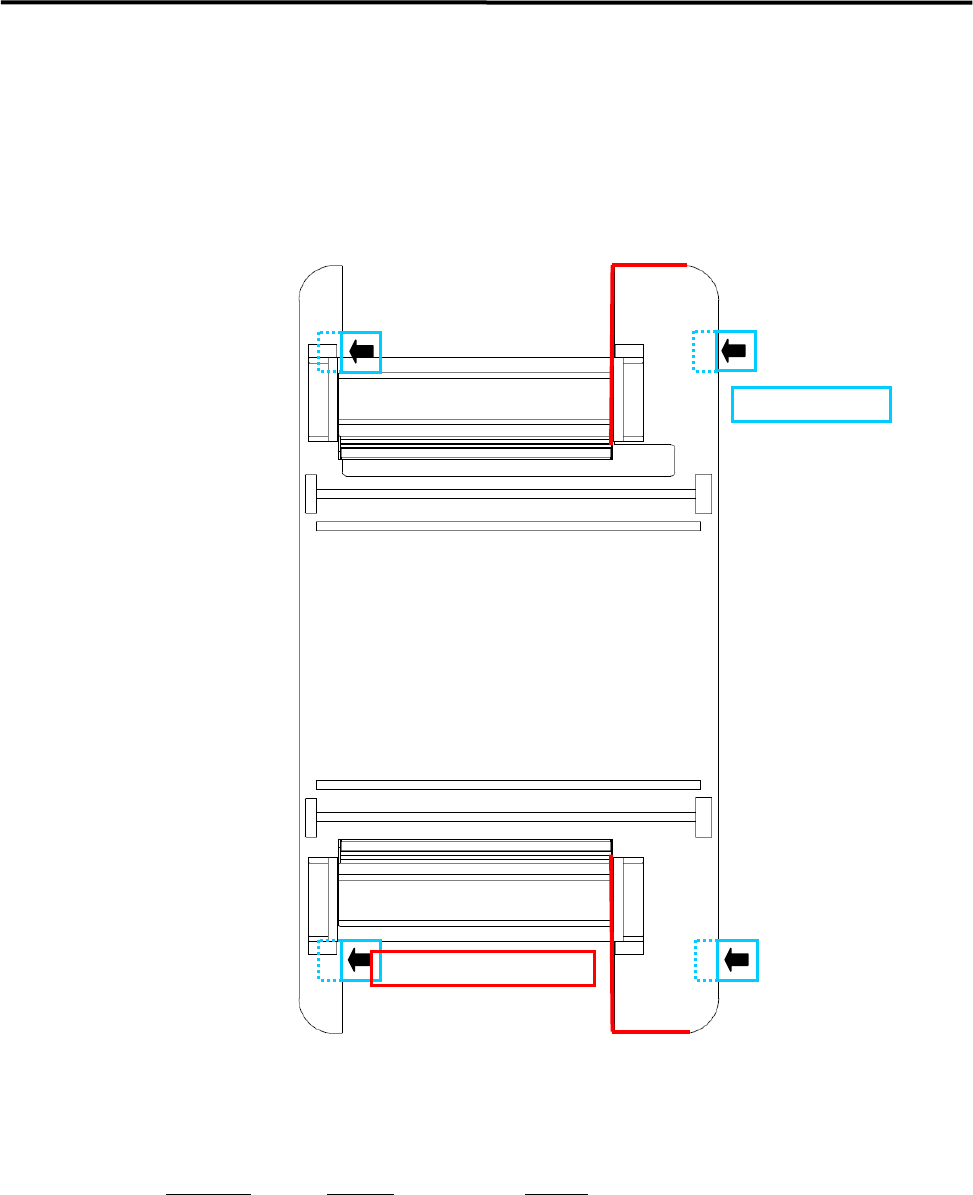
Jack-up Point
The four Jack-up points are determined considering the structure of M7 base face and balance ratio.
M8
NOTE: The hydraulic jacks must satisfy the following requirements.
Allowable load: 1.5 tons or higher
Hook size: 100mm or more (stroke)
Part Name
Part No. Remark
PLATE,BASE LG0-M8911-00X For plates 1 and 2
Jack-up Point
Prohibited Area for Jack-up