M8_ServiceManual_e.pdf - 第29页
1 Installation 1-15 Pre-Process and Post-Process of Machine Connecting Pre-Process and Post-Process When using other manufacturer’s m achines as the pre-process or post-process, connect them as shown i n the below diagra…
1 Installation
1-14
⑤ Disable all the parameters in other tab fields than [XY-axes]. Remove a check mark on each
parameters in [Conveyer], [Head], [Board Clamp], [ANS], [Feeder Bank], and [Lamp & Buzzer] (tabs
may vary due to mounter’s option settings.) in order to carry out only the selected parameters in
[XY-axes].
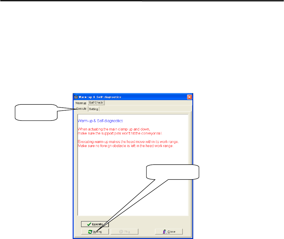
⑥ Select [Execute] and click <Ageing>.
When [Execute] tab is selected, the <Execute> button and the<Ageing> button are found at the
bottom of the window. Clicking the <Execute> button enables to perform warm-up only a single
cycle and sufficient ageing is not carried out.
⑦ Continue ageing for 5 to 10 minutes.
After 5 to 10 minutes, click the <Stop> button to stop ageing.
⑧ Wipe off excess grease.
Use a unwoven cloth to wipe off excess grease which is built up on ball-screw nuts, on linear guide
sliders, and both ends of each axis.
NOTE: Refer to Chapter 3 Mechanical Section for the location of each axis.
⑨ Check to be sure that the excess grease has not been scattered around.
Make sure the excess grease has not been stuck on sensors, cameras, conveyer and its belts, and ANC
When it has been stuck on these parts, remove it with unwoven cloth.
NOTE: Refer to Chapter 3 mechanical Section for more detail in cleaning of scan camera and mirror.
Ageing Button
Execute Tab
1 Installation
1-15
Pre-Process and Post-Process of Machine
Connecting Pre-Process and Post-Process
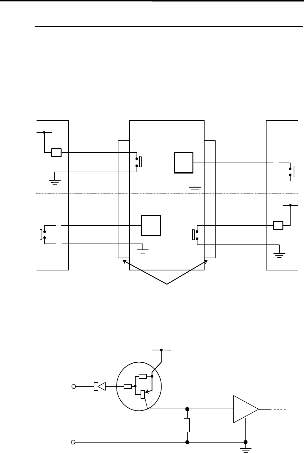
When using other manufacturer’s machines as the pre-process or post-process, connect them as shown in
the below diagram. No-voltage output (relay) is recommended for post-process.
Standard spec. : Upper half of the diagram.
SMEMA Interface spec. : Whole diagram.
*INPUT
CIRCUIT
*INPUT
CIRCUIT
2
1
CN2 CN1
Post-process
Connector (Cable side)
AMP
206044-1(plug)
66099-2 or equivalent (pin)
206070-1(cable clamp)
Connector (Mounter side)
AMP
206043-1(receptacle)
Mounter Pre-process
BOARD
AVAILABLE
BOARD
AVAILABLE
MACHINE
NOT READY
4.7KΩ
4.7KΩ
Input
terminal
*INPUT CIRCUIT
+5V
30VDC 1A or less
100VAC 0.5A or less
RELAY
RELAY
MACHINE
NOT READY
3
4
2
1
3
4
COM
1 Installation
1-16
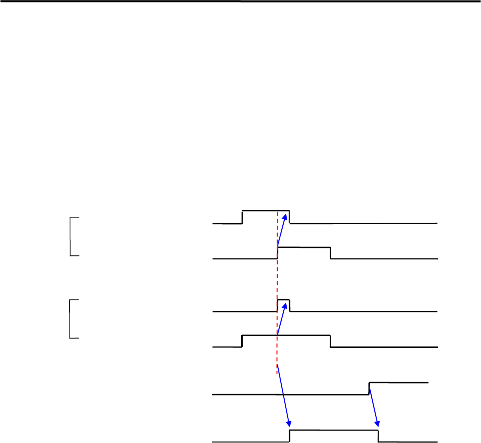
Sequence of Receiving PC board (Standard spec.)
① When the machine is ready to receive PC board, Permit Transfer (Machine Not Ready) is sent to
Pre-process machine.
② The transfer belt will be activated when the Permit Transfer and the Entrance Sensor turn on.
③ The Permit Transfer will be sent-off when Entrance Sensor turns on.
④ The transfer belt will be deactivated when the Arrival Sensor turns on.
⑤ “Conveyor Trouble” error happens if the Arrival Sensor does not turn on or the Entrance Sensor does
not turn off within 10 seconds after the transfer belt was activated.
⑥ Pressing START button restarts the operation paused by the error.
Permit Transfer to
Pre-process machine
(Machine Not Ready)
Permit Transfer to
Pre-process machine
(Machine Not Ready)
Transfer Belt
Arrival Sensor
Entrance Sensor
OR
Entrance Sensor
① ③
① ③
②
④