M8_ServiceManual_e.pdf - 第88页
4 Electrical Section 4-20 Serial I/O Operation Check LED ・ LED and Fuse location is same in all por ts (X70 to X76). ・ The fuse is a inset type. ・ Green LED does not light if the fuse has blown. Vision Port Stage Port No…
4 Electrical Section
4-19
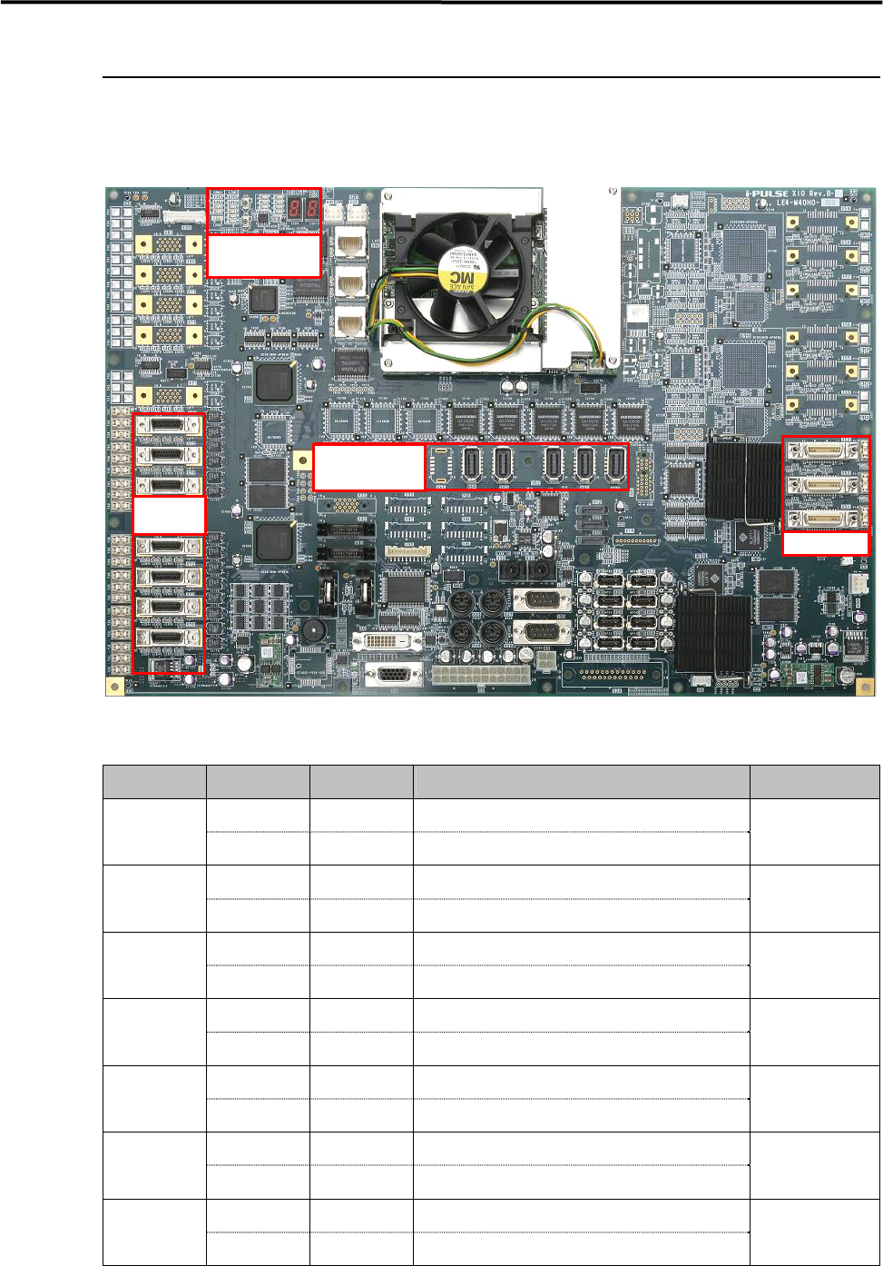
Xio BOARD Manual
The control board of M8 is equipped with the full digital multi function I/F included all control system for
the mounter.
<Xio Rev.B Top Side>
Serial I/O Port
Port No. Device No. DI/DO Control Boards
Device 1 DO Operation
Camera Illumination Control (Board・Beam F/R)
X70
Device 2 DI Monitor Head Vacuum Pressure Monitor
XiO.Hi
Device 3 DO Operation Each Safety Circuit Control
X71
Device 4 DI Monitor Each Safety Circuit Monitor
XiO.Mi8
Device 5 DO Operation Operation SW Indication (F)
X72
Device 6 DI Monitor
Operation SW Monitor (F)
XiO.Ui
Device 7 DO Operation Operation SW Indication (R)
X73
Device 8 DI Monitor Operation SW Monitor (R)
XiO.Ui
Device 9 DO Operation Conveyor System Control
X74
Device10 DI Monitor Conveyor Sensor Monitor
CIO7
Device11 DO Operation Feeder Bank (F)/CFB(F)/CTF(F) Control
X75
Device12 DI Monitor Feeder Bank (F)/CFB(F)/CTF(F)
XiO.Fi / XiO.Ti
Device13 DO Operation Feeder Bank (R)/CFB(R)/CTF(R) Control
X76
Device14 DI Monitor Feeder Bank (R)/CFB(R)/CTF(R)
XiO.Fi / XiO.Ti
Vision Port
Motion Port
Operation Check
LED
Serial I/O
Port
4 Electrical Section
4-20
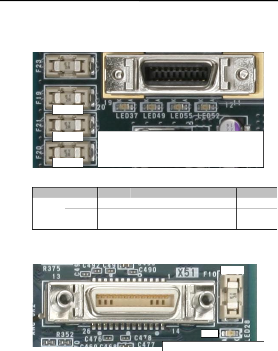
Serial I/O Operation Check LED
・LED and Fuse location is same in all ports (X70 to X76).
・The fuse is a inset type.
・Green LED does not light if the fuse has blown.
Vision Port
Stage Port No. Camera No. Connection Part Name Access Camera
X51 Camera 1 Board Camera Board Camera
X52 Camera 2 Beam Camera 1 Beam Camera (F)
Stage A
X53 Camera 3 Beam Camera
2
Beam Camera (R)
・LED and Fuse location is same in all ports (X51 to X53).
・The fuse is a insert type.
・Green LED does not light if the fuse has blown.
Replacement Fuse; LE4-M65W1-00X (Littel Fuse; 0453 002)
Replacement Buttery; LE4-M65W2-00X (CR2032)
① Light in Yellow; Serial I/O communication is being carried out.
② Light in Green; Supplying +12V ⇒ Fuse A
③ Light in Green; Supplying +24V ⇒ Fuse B
④ Light in Green; Supplying +5V ⇒ Fuse C
Fuse A
Fuse B
Fuse C
① ②
③
④
Fuse
LED
Li
g
h
t
in Green
;
Su
pp
l
y
in
g
+12V
⇒
Fuse
4 Electrical Section
4-21
Motion Port
Port No. Drive No. DI/DO Control Motor
Access AMP
Drive 1 - Control X1 Axis Motor X1 Axis AMP
X60
Drive 2 - Control X2 Axis Motor X2 Axis AMP
Drive 3 - Control Y Axis Motor Y Axis AMP
X61
Drive 4 - Control W Axis Motor W Axis AMP
Drive 5 6/8 Control Z and T Axes Motors (Front Unit) Z/T AMP ( 1
~
4 )
X62
Drive 6 4/8 Control Z and T Axes Motors (Rear Unit) Z/T AMP ( 5
~
8 )
Drive 7 - CTF (F), Control Z Axis Motor CTF (F) Z AMP
X63
Drive 8 - CTF (F), Control Y Axis Motor CTF (F) Y AMP
Drive 9 - CTF (R), Control Z Axis Motor CTF (R) Z AMP
X64
Drive10 - CTF (R), Control Y Axis Motor CTF (R) Y AMP
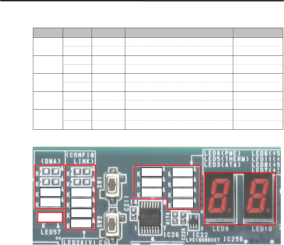
Operation Check LED
① DMA Transfer LED ; Transferring → Yellow
LED21 ; Vision Stage A Vision Data Transfer
LED27 ; Motion Axis Data Transfer
② Initialization Completion LED ; After initialization → Yellow
LED20 ; Vision Stage A
LED26 ; Motion
LED51 ; Serial I/O
LED54 ; Encoder, Trigger, Laser I/F
③ CPU Operation Check LED
LED 4 ; Red Color → Power Saving Mode
LED 5 ; Red Color → CPU Module Temperature Abnormal
LED 3 ; Yellow Color → Accessing HDD
④ ATX Power Supply Voltage LED ; Normal → Green
LED 6 ; +5V Standby
LED11; +3.3V
LED 8 ; +5V
LED 7 ; +12V
⑤ 7Segments LED
“c0” sign will be indicated after Windows has booted up normally.
Usually, the indication will be changing ,『2A』⇒・・・・・⇒『60』⇒・・・・・⇒『c0』.
The detail of other indications is shown in the next page.
LED57
③
④
②
①
⑤
LED27
LED21
LED54
LED51
LED26
LED20
LED 7
LED 8LED 3
LED 5
LED 4
LED11
LED 6