M8_ServiceManual_e.pdf - 第95页
4 Electrical Section 4-27 PCB arrival sensor ● LE4-M951H-00X FIBER SENSOR FX-100 Series (SUNX) ■ Adjusting Method ① Sensor Installation and Adjust ment The optical receiver of PCB Arrival Sensor has to be set within 60 t…
4 Electrical Section
4-26
Adjustment of Board Detection Sensors
This section explains how to adjust the sensitivity of the board detection sensors.
Entrance sensor / Exit sensor
● LC6-M90H1-00X PHOTO SENSOR E3Z-D81 (OMRON)
■ Adjusting Method
① Place a PCB on the conveyor belt in the direction in which PCBs will be placed for actual production
operation.
② Turn the sensor’s sensitivity volume counter-clockwise (toward “min”) as far as it will go, to set the
sensitivity to the minimum level.
*The volume can be turned 3/4 turns. Turning it clockwise (toward “max”) increases the sensitivity
and turning it counter-clockwise (toward “min”) decreases it.
③ With the PCB detected by the sensor, turn the volume clockwise (toward “max”) gradually, up to the
point (A) where the orange LED (operation indicator) begins to light up.
④ Remove the PCB and turn the volume clockwise (toward “max”), up to the point (B) where the orange
LED begins to light up. (If the orange LED does not light up even if the volume is turned clockwise as
far as it will go, the position to which the volume has been turned clockwise as far as it will go will be
considered to be position (B).)
⑤ The center position between the positions (A) and (B) is set as the adjustment position. With the PCB
detected at that position, check that both orange and green LEDs light up at the same time. Also check
that only the green LED lights up when the PCB is removed.
⑥ When the conveyor cover is provided because of the safety spec., attach a black rubber sheet to the
sensor detection position on the bottom of the cover to prevent false detection.
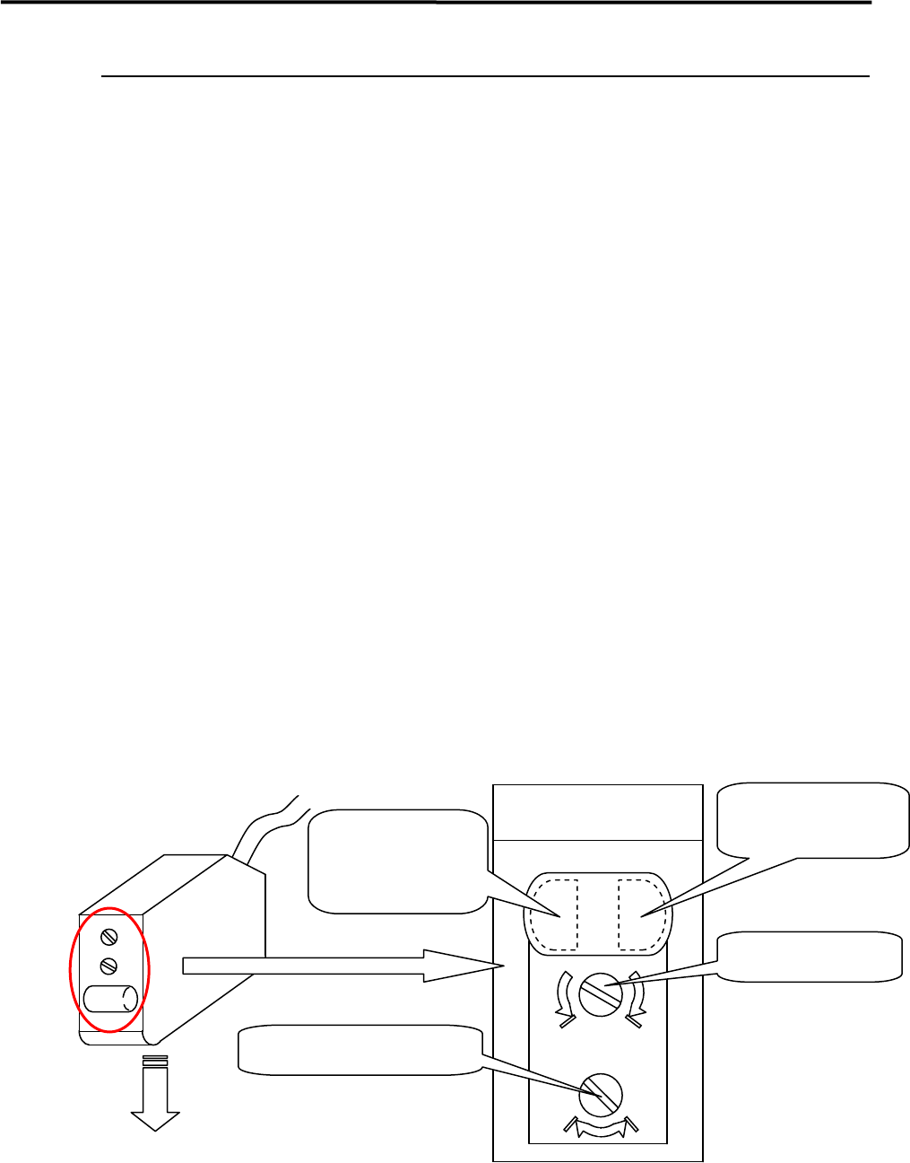
NOTE: Make sure that the operation selector switch is set to “L” (ON when light is entered).
max min
DL
Sensor emitting direction
Enlarged View of Sensor
(Shown in upside down
direction)
Operation indicator
(Orange LED)
Operation-stable
indicator
(Green LED)
Sensitivity volume
Operation selector switch
4 Electrical Section
4-27
PCB arrival sensor
● LE4-M951H-00X FIBER SENSOR FX-100 Series (SUNX)
■ Adjusting Method
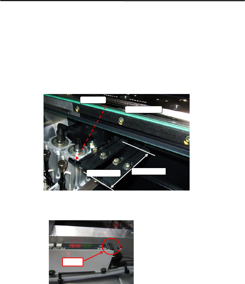
① Sensor Installation and Adjustment
The optical receiver of PCB Arrival Sensor has to be set within 60 to 70 mm from the conveyor guide,
and the optical axis has not to be interfered by any parts of the conveyor.
NOTE: It should be confirmed that nothing interferes with the optical axis by the minimum conveyor width.
② Confirm the harness of the fiber sensor is locked.
NOTE: If it has not been locked properly, the function might be unstable.
The sensor harness must be locked certainly after it has been inserted.
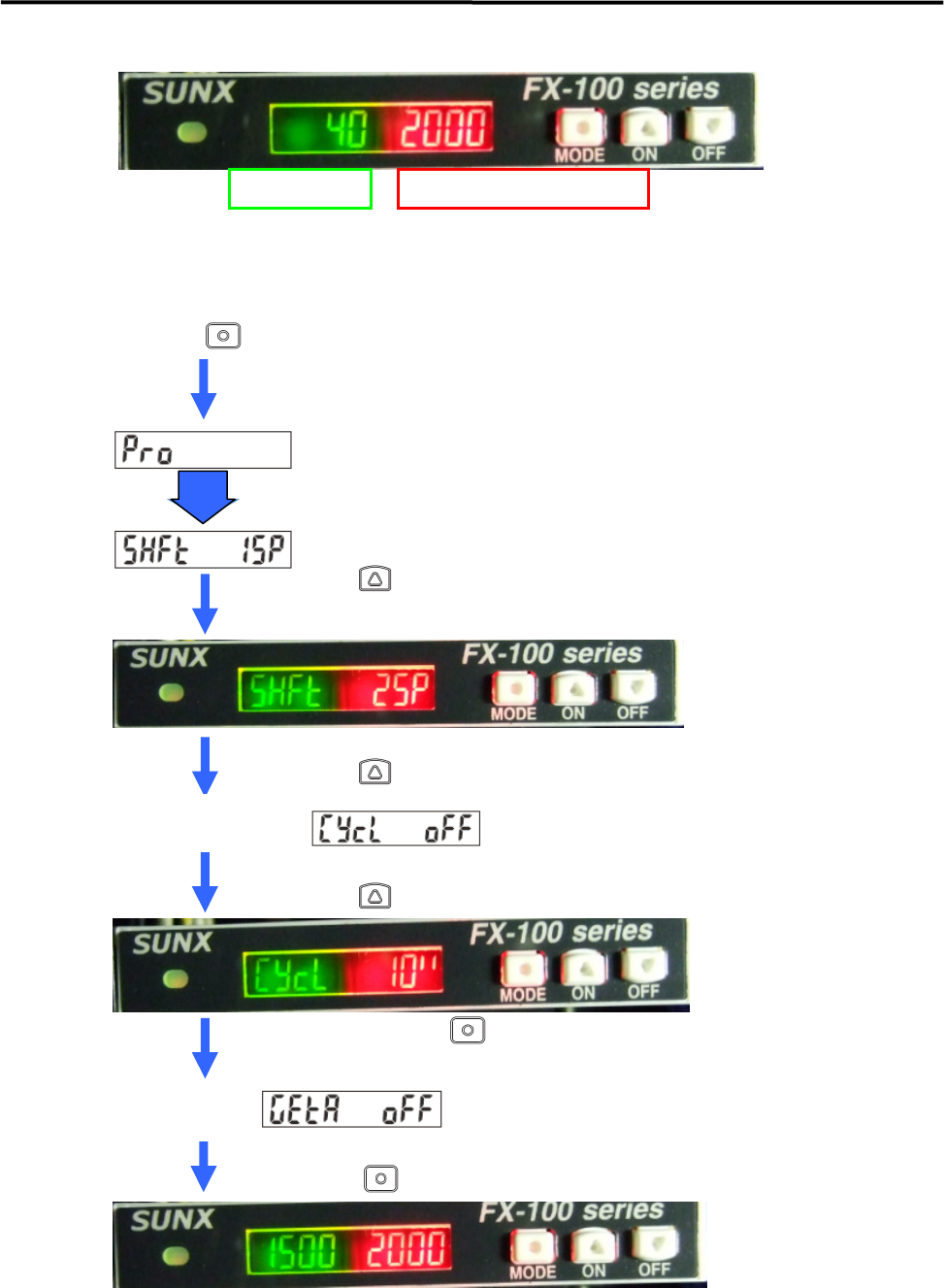
③ Check the indication value of the received optical light.
The indication value should be from 2000 to 3800.
If it is lower than 2000, it is necessary to readjust the fixed position of the sensor in Item ①.
*Do not change the threshold value (the factory setting; “40”).
Transmitter
Receiver
O
p
tical Axis
60mm
~
70mm
LOCK
4 Electrical Section
4-28
④ Set up the threshold follow-up cycle of the fiber amplifier.
Set “Shift Quantity” to 25% and “Follow-up Cycle” to 10 seconds.
Press key more than 4 seconds in the normal detection condition.
Proceed to “ Pro Mode” and change to threshold follow-up cycle setting automatically.
Press key to show “ 25P” .
Press key two times.
【NOTE】Check that the threshold has been 25% to the received light value.
The threshold will be still low just after setting.
Threshold value Received Optical Light Value
Auto
Current Threshold
Follow-up Cycle Setting
(In case of “OFF” setting)
Press key and set it to “10 seconds”.
Fix the setting by key.
Current GETA
Function Setting
(In case of “OFF” setting)
Press key six times or keep pressing for two seconds.