M8_ServiceManual_e.pdf - 第49页
3 Mechanical Section 3-9 ■ Applying Silicon Grease After the nozzle is cleaned, it must be coated with silicon grease. ● Nozzle outer surface Apply a slight amount of grease to the outer surface (i ndicated by dotted lin…

3 Mechanical Section
3-8
■ Inspection of Suction Pad (Nozzle No. P017, P018, P019, P020)
Check that the rubber suction pad located at the nozzle tip is free from scratches and cracks. If they are
found on the pad, replace the pad with a new one.
ACTION: Remove the old pad, apply silicon grease to the inner surface of a new pad, and then install it in the nozzle.
Part Name
Part No. Remark
RUBB.PAD17 LG0-M77A0-00X Suction pad for P017
RUBB.PAD18 LG0-M77A1-00X Suction pad for P018
RUBB.PAD19 LG0-M77A2-00X Suction pad for P019
RUBB.PAD20 LG0-M77A9-00X Suction pad for P020
GREASE SILICON LG0-M89AB-00X Silicone Grease
3 Mechanical Section
3-9
■ Applying Silicon Grease
After the nozzle is cleaned, it must be coated with silicon grease.
● Nozzle outer surface
Apply a slight amount of grease to the outer surface (indicated by dotted lines in the above illustration), and
then wipe it off with a dry cloth.
NOTE: Silicon grease must be applied so that it forms a thin film on the surface.
● Suction pad
Application of oil content is needed to prevent deterioration of the rubber. Apply a slight amount of grease
to the outer surface of the suction pad, and then wipe it off with a dry cloth.
NOTE: Silicon grease must be applied so that it forms a thin film on the surface.
Do not apply excessive amounts of grease. This may cause collection of dirt or dust in
the air passage and on placed components, resulting in component placement failure.
● Inspection interval
Approx. once a month
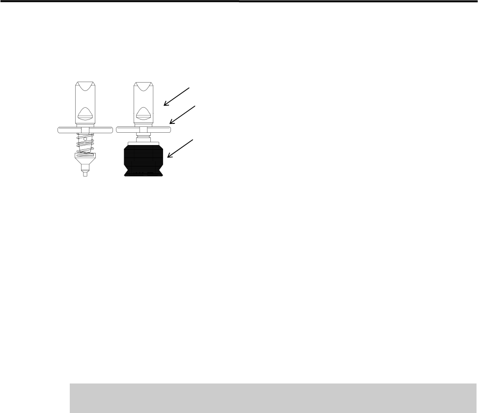
Suction pad
Nozzle ID sticker
Apply silicon grease.

3 Mechanical Section
3-10
Nozzle Holder
● Checking the nozzle holder escape
After grease is applied to the nozzle’s outer surface, attach the nozzle to the head and check the condition of
the nozzle holder escape.
NOTE: When the nozzle is placed in the head (nozzle holder), it can slide a few millimeters vertically. This nozzle
sliding movement is called nozzle holder escape.
ACTION:
① Attach the nozzle to the head.
② Push the nozzle gently with fingers up to the top dead center of the nozzle holder escape.
③ Release fingers gently and check that the nozzle returns to the lower dead center smoothly.
NOTE: If the nozzle holder escape is not smooth, there may be problems with component suction and placement. If
the nozzle gets caught or does not move smoothly, check the nozzle holder and nozzle’s inner/outer
surfaces for collection of foreign matter or scratches.
● Inspection interval
Approx. once a week