M8_ServiceManual_e.pdf - 第87页
4 Electrical Section 4-19 Xio BOARD Manual The control board of M8 is equipp ed with the full dig ital multi function I/F included all control system for the mounter. <Xio Rev.B Top Side> Serial I/O Port Port No. D…

4 Electrical Section
4-18
■ Device 14
Rear Feeder Bank
Address Bit No. Signal Name Address Bit No. Signal Name
0000h 0 Device No. Bit 0 0004h 0
1 Device No. Bit 1 1
2 Device No. Bit 2 2
3 Device No. Bit 3 3 CTF (R) Shutter Open (R)
4 Device Added Information Bit 0 4 CTF (R) Shutter Close (R)
5 Device Added Information Bit 1 5 CTF (R) Shutter Open (L)
6 Device Added Information Bit 2 6 CTF (R) Shutter Close (L)
7 Output Register Value Bit 0 7 CTF (R) Stocker Pallet Interlock
0001h 0 Output Register Value Bit 1 0
1 Output Register Value Bit 2 1
2 Output Register Value Bit 3 2 CTF (R) Pallet Existence
3 Output Register Value Bit 4 3 CTF (R) Stocker Area
4 Input Register Value Bit 0 4 CTF(R) Cover Open
5 Input Register Value Bit 1 5 CTF (R) Setup Switch
6 Input Register Value Bit 2 6 CTF (R) Thermo Sensor
7 Input Register Value Bit 3 7 CTF (R) Hook Position 1
0002h 0 TI BOARD (R) ID 0 0006h 0 CTF (R) Hook Position 2
1 TI BOARD (R) ID 1 1 CTF (R) pallet Detect in Stocker
2 TI BOARD (R) ID 2 2 CTF (R) pallet Stopper (R)
3 TI BOARD (R) ID 3 3 CTF (R) Pallet Stopper (L)
4 TI BOARD (R) ID 4 4
5 TI BOARD (R) ID 5 5
6 TI BOARD (R) ID 6 6
7 TI BOARD (R) ID 7 7
0003h 0 TI BOARD (R) ID 8 0007h 0
1 TI BOARD (R) ID 9 1
2 TI BOARD (R) ID 10 2
3 TI BOARD (R) ID 11 3
4 TI BOARD (R) ID 12 4
5 TI BOARD (R) ID 13 5
6 TI BOARD (R) ID 14 6
7 TI BOARD (R) ID 15 7
4 Electrical Section
4-19
Xio BOARD Manual
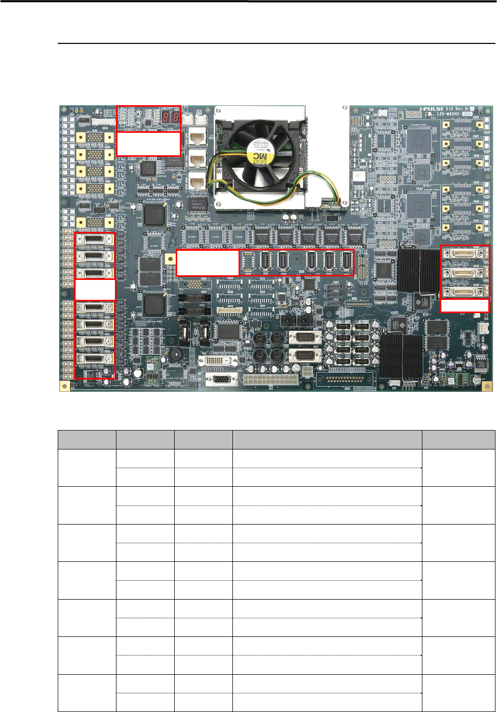
The control board of M8 is equipped with the full digital multi function I/F included all control system for
the mounter.
<Xio Rev.B Top Side>
Serial I/O Port
Port No. Device No. DI/DO Control Boards
Device 1 DO Operation
Camera Illumination Control (Board・Beam F/R)
X70
Device 2 DI Monitor Head Vacuum Pressure Monitor
XiO.Hi
Device 3 DO Operation Each Safety Circuit Control
X71
Device 4 DI Monitor Each Safety Circuit Monitor
XiO.Mi8
Device 5 DO Operation Operation SW Indication (F)
X72
Device 6 DI Monitor
Operation SW Monitor (F)
XiO.Ui
Device 7 DO Operation Operation SW Indication (R)
X73
Device 8 DI Monitor Operation SW Monitor (R)
XiO.Ui
Device 9 DO Operation Conveyor System Control
X74
Device10 DI Monitor Conveyor Sensor Monitor
CIO7
Device11 DO Operation Feeder Bank (F)/CFB(F)/CTF(F) Control
X75
Device12 DI Monitor Feeder Bank (F)/CFB(F)/CTF(F)
XiO.Fi / XiO.Ti
Device13 DO Operation Feeder Bank (R)/CFB(R)/CTF(R) Control
X76
Device14 DI Monitor Feeder Bank (R)/CFB(R)/CTF(R)
XiO.Fi / XiO.Ti
Vision Port
Motion Port
Operation Check
LED
Serial I/O
Port
4 Electrical Section
4-20
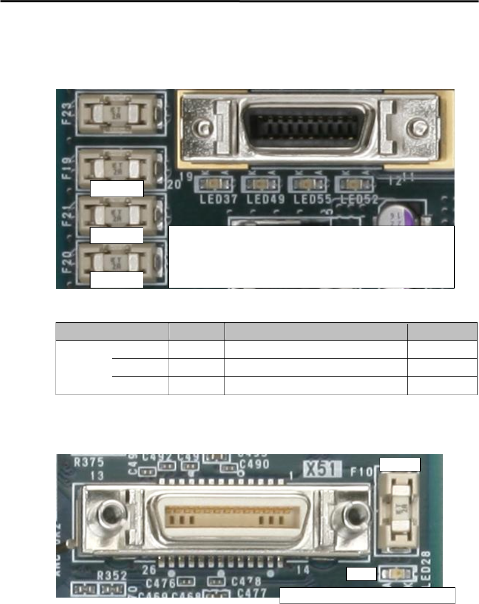
Serial I/O Operation Check LED
・LED and Fuse location is same in all ports (X70 to X76).
・The fuse is a inset type.
・Green LED does not light if the fuse has blown.
Vision Port
Stage Port No. Camera No. Connection Part Name Access Camera
X51 Camera 1 Board Camera Board Camera
X52 Camera 2 Beam Camera 1 Beam Camera (F)
Stage A
X53 Camera 3 Beam Camera
2
Beam Camera (R)
・LED and Fuse location is same in all ports (X51 to X53).
・The fuse is a insert type.
・Green LED does not light if the fuse has blown.
Replacement Fuse; LE4-M65W1-00X (Littel Fuse; 0453 002)
Replacement Buttery; LE4-M65W2-00X (CR2032)
① Light in Yellow; Serial I/O communication is being carried out.
② Light in Green; Supplying +12V ⇒ Fuse A
③ Light in Green; Supplying +24V ⇒ Fuse B
④ Light in Green; Supplying +5V ⇒ Fuse C
Fuse A
Fuse B
Fuse C
① ②
③
④
Fuse
LED
Li
g
h
t
in Green
;
Su
pp
l
y
in
g
+12V
⇒
Fuse