M8_ServiceManual_e.pdf - 第43页
3 Mechanical Section 3-3 Head Manifold Section ■ Air Passage To maintain the designed accuracy and com ponent-placem ent rate of the m achine, clean the air passage between the air filter assy. and nozzle ho lder periodi…
3 Mechanical Section
3-2
Head Manifold Section
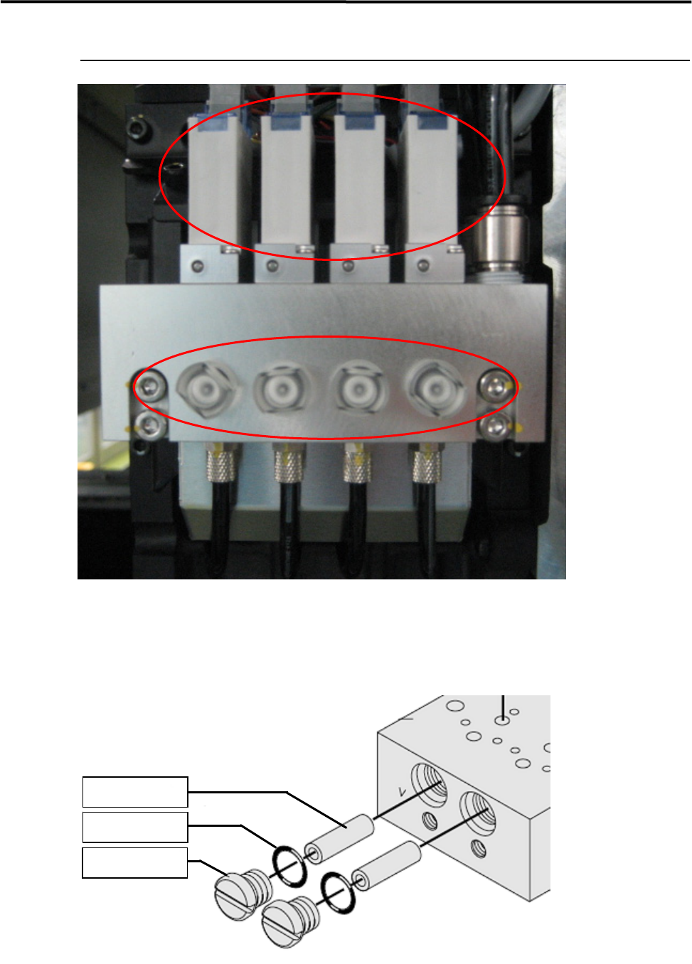
① VALVE (LE4-M71A1-A0X)
② FILTER (K46-M8527-C0X)
①
②
FILTER
K46-M8527-C0X
O-RING
LE4-M71A1-D0X
FILTER CAP
LE4-M71A1-C0X

3 Mechanical Section
3-3
Head Manifold Section
■ Air Passage
To maintain the designed accuracy and component-placement rate of the machine, clean the air passage
between the air filter assy. and nozzle holder periodically.
ACTION: Carry out vacuum break operation for a few seconds with the nozzle removed.
● Cleaning interval
Approx. once a week
■ Air Filter
ACTION: Remove the filter cap from the ejector manifold, and remove the filter element from inside and check it for
dirty. If it has been excessively dirty, replace it with a new one. And, replace O-rings if it has been
deformed, because it will cause air leakage.
NOTE: When put the filter cap back on the manifold, handle the cap carefully and also pay attention not to fasten it
too much, because the filter cap is made of polycarbonate.
● Inspection interval
Once a week, and when a choking error occurs
Part Name
Part No. Note
FILTER K46-M8527-C0X Filter
FILTER CAP LE4-M71A1-C0X Air Cap
O-RING LE4-M71A1-D0X O-Ring
■ Vacuum Generator
ACTION: Breakdown visually checks the silencer element, and if it is excessively dirty, replace it with a new one.
Also measure the maximum air pressure to inspect whether the vacuum generator can generate vacuum
properly.) Inspection for Head/Nozzle Clogging and Solenoid Valve
● Inspection interval
Once a week
Part Name
Part No. Remark Note
MUFFLER LE4-M71A1-H0X Muffler
MUFFLER ASSY. LE4-M71A1-F0X Muffler Assy.

3 Mechanical Section
3-4
Inspection for Head/Nozzle Clogging and Solenoid Valve
Breakdown
The following inspection must be carried out approximately once a week.
■ Inspection of Solenoid Valve
The switching valve of the solenoid valve may catch foreign matter causing air leakage. Air leakage will
turn the suction ON even if it is turned OFF.
As a result, the suction cannot be turned OFF after a component is mounted, and components may be
returned instead of being mounted on the PCB.
● Inspecting by selecting [Manual] – [Meas. Air pressure]
①Checking the maximum air pressure
Turn ON the suction and press the nozzle tip
with fingers to check the air pressure. The air pressure is
sati
sfactory if it is “580” or higher.
②Checking the head for clogging
With no nozzles placed in the head, turn ON the suction to check the air pressure. Approx. “40”is the
standard pressure level in this condition. An error will occur if the air pressure is “120” or higher during
vacuum check performed after nozzle replacement.
③Checking the nozzle for clogging
With nozzles placed in the head, turn ON the suction to check the air pressure. “Nozzle clog criteria” has
been set for each nozzle. The air pressure must be below the criteria. If it is not, the nozzle will be
considered to be clogged and an error will occur.
④Checking the solenoid valve for switching failure
Turn OFF the suction and check for change in the air pressure.
- Press the head/nozzle tip with fingers and check for change in the air pressure.
- Turn ON and OFF the suction a few times and check for change in the air pressure.
If the air pressure changes even though the suction is OFF, air is probably leaking from the suction solenoid
valve.
NOTE: Do not disassemble the solenoid valve. Manufacturer’s guarantee will be ineffective if the solenoid valve is
disassembled.
Part Name
Part No. Remark
SOL.VALVE LC1-M71A1-10X Solenoid Valve
NOTE: For official inspection, use of a digital vacuum meter is necessary to check accuracy of the displayed air
pressure value.
Part Name
Part No. Remark
MANOMETER ASSY. LC1-M89A5-00X Vacuum Gauge Set