M8_ServiceManual_e.pdf - 第25页
1 Installation 1-11 Jack-up Point The four Jack-up points are determined considering the structure of M7 base face and balance ratio. M8 NOTE: The hydraulic jacks m ust satisfy the followi ng requirements. Allowable load…
1 Installation
1-10
Supplementary Explanation for Installation
When setting up a production line, level adjustment and line positioning of the machine may be carried out
at the same time. However, to fine-adjust the machine position with the machine level, i-PULSE
recommends that the machine be roughly positioned to the production line first, and then be leveled and
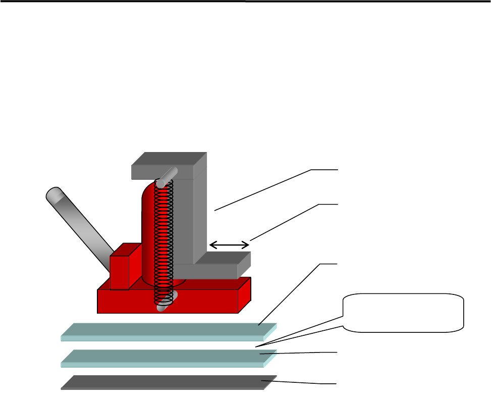
positioned accurately using the following four sets comprising a hydraulic jack and plates.
ACTION:
① Bond the non-slip base rubber with base plate 2.
② Apply grease between base plates 1 and 2 for lubrication purposes.
③ Place a plate set near each machine jack-up point (four points).
④ Place a jack on each plate set and jack up the machine.
⑤ Adjust each jack so that the machine is level.
⑥ Fine-adjust the position of the machine while the machine is jacked up. (The machine can be moved
lengthwise and crosswise with help of grease applied between the plates.)
Hydraulic jack
Base plate 1
Base plate 2
Base rubber
Apply grease
between the
p
lates.
Hook stroke
1 Installation
1-11
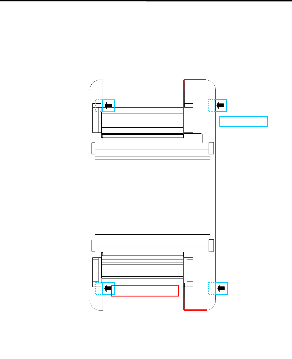
Jack-up Point
The four Jack-up points are determined considering the structure of M7 base face and balance ratio.
M8
NOTE: The hydraulic jacks must satisfy the following requirements.
Allowable load: 1.5 tons or higher
Hook size: 100mm or more (stroke)
Part Name
Part No. Remark
PLATE,BASE LG0-M8911-00X For plates 1 and 2
Jack-up Point
Prohibited Area for Jack-up
1 Installation
1-12
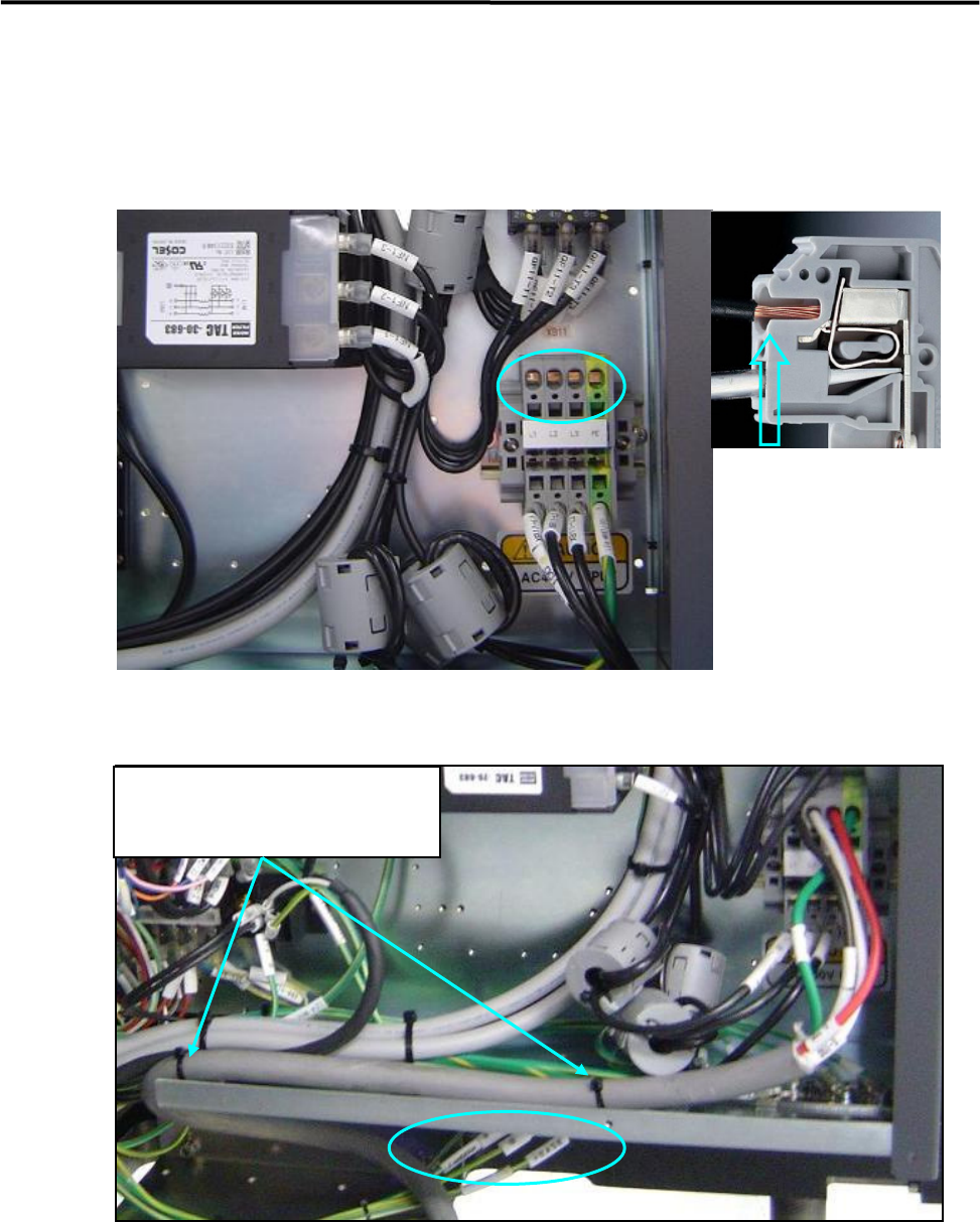
Put cable clamps on screw holes, and
fasten the power cable with cable ties.
Power Cable Wiring
Route the power cable to outside the mounter through the rectangle cable at the lower part of the rear cover
(see Fig 1 and 2).
In the above picture, circle holes are insertions of power cables and square holes are insertions of tools. At
first, insert a driver to the square hole and press down the driver, insert a power cable to the circle hole, and
pull the driver out, then the cable will be clamped.
The power cable should be secured inside the mounter to prevent accident disconnection by pulling on the
cable outside the mounter.
To fasten the power cable with cable ties, first attach cable clamp to unused screw holes then insert cable
ties through the cable clamps. Or bind the power cable to the terminal-panel leg with cable ties.
・Recommended Driver
4mm minus Driver
・Recommended Cable
3.5 ㎟ / Withstand Voltage 600V
・Length of peeling off cables
12mm