M8_ServiceManual_e.pdf - 第89页
4 Electrical Section 4-21 Motion Port Port No. Drive No. DI/DO Control Motor Access AMP Drive 1 - Control X1 Axis Motor X1 Axis AMP X60 Drive 2 - Control X2 Axis Motor X2 Axis AMP Drive 3 - Control Y Axis Motor Y Axis AM…
4 Electrical Section
4-20
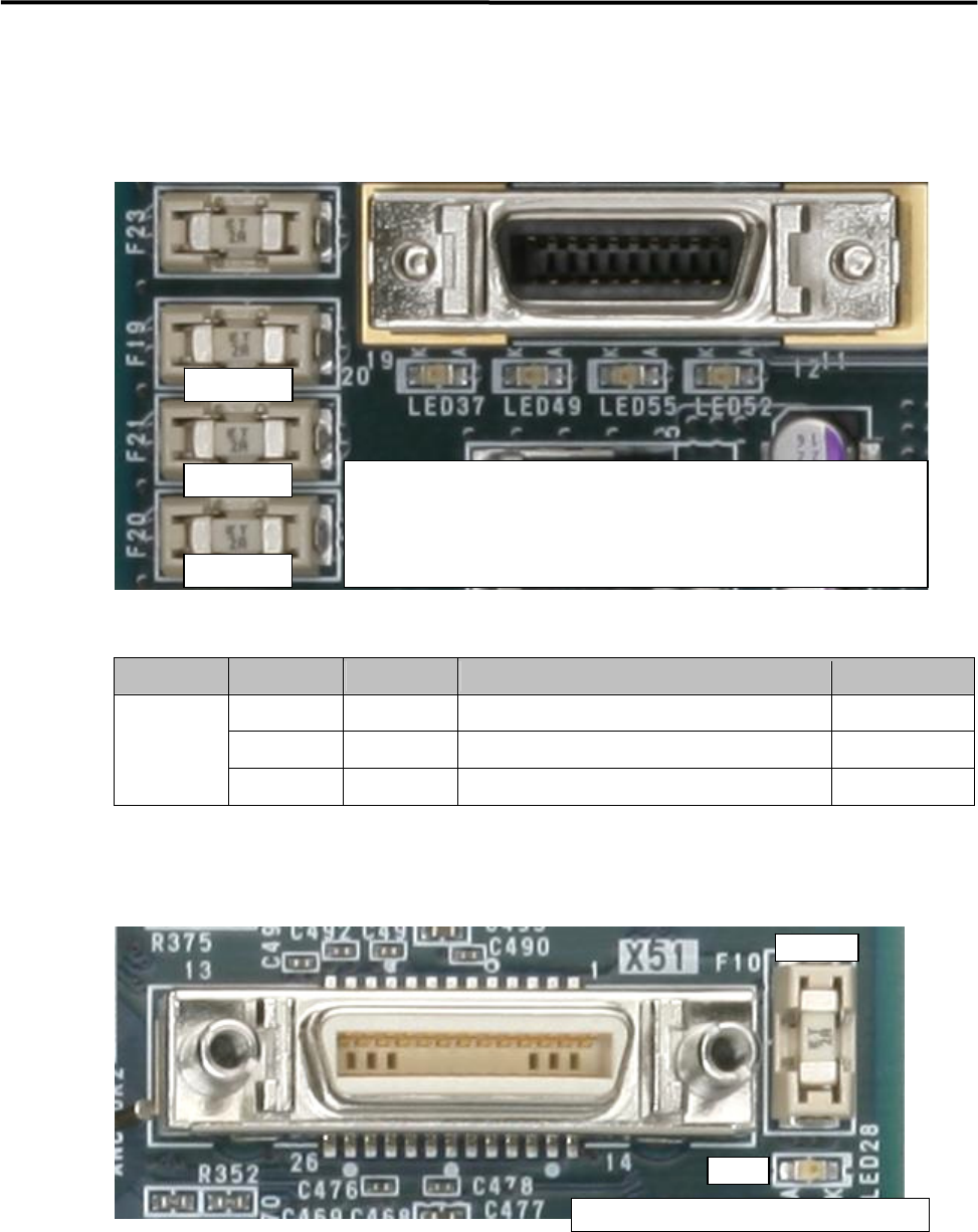
Serial I/O Operation Check LED
・LED and Fuse location is same in all ports (X70 to X76).
・The fuse is a inset type.
・Green LED does not light if the fuse has blown.
Vision Port
Stage Port No. Camera No. Connection Part Name Access Camera
X51 Camera 1 Board Camera Board Camera
X52 Camera 2 Beam Camera 1 Beam Camera (F)
Stage A
X53 Camera 3 Beam Camera
2
Beam Camera (R)
・LED and Fuse location is same in all ports (X51 to X53).
・The fuse is a insert type.
・Green LED does not light if the fuse has blown.
Replacement Fuse; LE4-M65W1-00X (Littel Fuse; 0453 002)
Replacement Buttery; LE4-M65W2-00X (CR2032)
① Light in Yellow; Serial I/O communication is being carried out.
② Light in Green; Supplying +12V ⇒ Fuse A
③ Light in Green; Supplying +24V ⇒ Fuse B
④ Light in Green; Supplying +5V ⇒ Fuse C
Fuse A
Fuse B
Fuse C
① ②
③
④
Fuse
LED
Li
g
h
t
in Green
;
Su
pp
l
y
in
g
+12V
⇒
Fuse
4 Electrical Section
4-21
Motion Port
Port No. Drive No. DI/DO Control Motor
Access AMP
Drive 1 - Control X1 Axis Motor X1 Axis AMP
X60
Drive 2 - Control X2 Axis Motor X2 Axis AMP
Drive 3 - Control Y Axis Motor Y Axis AMP
X61
Drive 4 - Control W Axis Motor W Axis AMP
Drive 5 6/8 Control Z and T Axes Motors (Front Unit) Z/T AMP ( 1
~
4 )
X62
Drive 6 4/8 Control Z and T Axes Motors (Rear Unit) Z/T AMP ( 5
~
8 )
Drive 7 - CTF (F), Control Z Axis Motor CTF (F) Z AMP
X63
Drive 8 - CTF (F), Control Y Axis Motor CTF (F) Y AMP
Drive 9 - CTF (R), Control Z Axis Motor CTF (R) Z AMP
X64
Drive10 - CTF (R), Control Y Axis Motor CTF (R) Y AMP
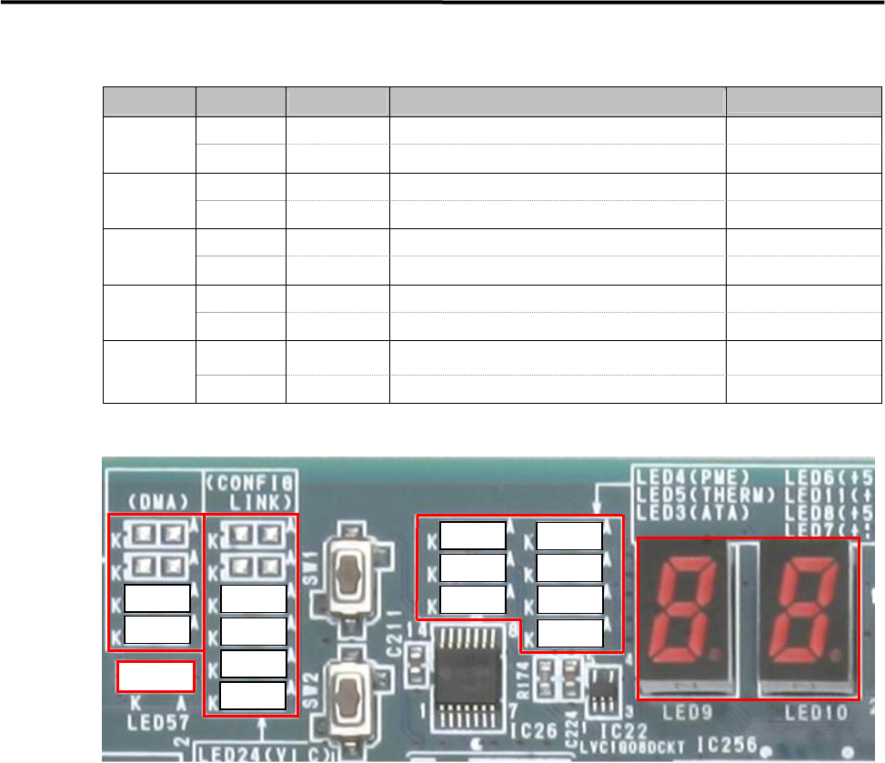
Operation Check LED
① DMA Transfer LED ; Transferring → Yellow
LED21 ; Vision Stage A Vision Data Transfer
LED27 ; Motion Axis Data Transfer
② Initialization Completion LED ; After initialization → Yellow
LED20 ; Vision Stage A
LED26 ; Motion
LED51 ; Serial I/O
LED54 ; Encoder, Trigger, Laser I/F
③ CPU Operation Check LED
LED 4 ; Red Color → Power Saving Mode
LED 5 ; Red Color → CPU Module Temperature Abnormal
LED 3 ; Yellow Color → Accessing HDD
④ ATX Power Supply Voltage LED ; Normal → Green
LED 6 ; +5V Standby
LED11; +3.3V
LED 8 ; +5V
LED 7 ; +12V
⑤ 7Segments LED
“c0” sign will be indicated after Windows has booted up normally.
Usually, the indication will be changing ,『2A』⇒・・・・・⇒『60』⇒・・・・・⇒『c0』.
The detail of other indications is shown in the next page.
LED57
③
④
②
①
⑤
LED27
LED21
LED54
LED51
LED26
LED20
LED 7
LED 8LED 3
LED 5
LED 4
LED11
LED 6

4 Electrical Section
4-22
The detail of 7 segments LED indications is shown in the below table.
Diagnostic
Code
Meaning
Diagnostic
Code
Meaning
02h Verify processor mode 41h Initialize extended memory for RomPilot
03h Disable Non-Maskable Interrupt (NMI) 42h Initialize interrupt vectors
04h Get CPU type 45h POST device initialization
06h Initialize system hardware 46h Check ROM copyright notice
07h Disable shadow and execute code from the ROM. 47h Initialize I2O support
08h Initialize chipset with initial POST values 48h Check video configuration against CMOS
09h Set IN POST flag 49h Initialize PCI bus and devices
0Ah Initialize CPU registers 4Ah Initialize all video adapters in system
0Bh Enable CPU cache 4Bh QuietBoot start
0Ch Initialize caches to initial POST values 4Ch Shadow video BIOS ROM
0Eh Initialize I/O components 4Eh Display BIOS copyright notice
0Fh Initialize the local bus IDE 4Fh Initialize MultiBoot
10h Initialize Power Management 50h Display CPU type and speed
11h Load alternate registers with initial POST values 51h Initialize EISA board
12h Restore CPU control word during warm boot 52h Test keyboard
13h Initialize PCI Bus Mastering devices 54h Set key click if enabled
14h Initialize keyboard controller 55h Enable USB devices
16h BIOS ROM checksum 58h Test for unexpected interrupts
17h Initialize cache before memory autosize 59h Initialize POST display service
18h 8254 timer initialization 5Ah Display prompt "Press F2 to enter SETUP"
1Ah 8237 DMA controller initialization 5Bh Disable CPU cache
1Ch Reset Programmable Interrupt Controller 5Ch Test RAM between 512 and 640 KB
20h Test DRAM refresh 60h Test extended memory
22h Test 8742 Keyboard Controller 62h Test extended memory address lines
24h Set ES segment register to 4 GB 64h Jump to UserPatch1
28h Autosize DRAM 66h Configure advanced cache registers
29h Initialize POST Memory Manager 67h Initialize Multi Processor APIC
2Ah Clear 512 KB base RAM 68h Enable external and CPU caches
2Ch RAM failure on address line xxxx 69h Setup System Management Mode (SMM) area
2Eh RAM failure on data bits xxxx of low byte of memory
bus
6Ah
Display external L2 cache size
2Fh Enable cache before system BIOS shadow 6Bh Load custom defaults
32h Calculate CPU speed 6Ch Display shadow-area message
33h Initialize POST Dispatch Manager 6Eh Display possible high address for UMB recovery
34h Test CMOS RAM and RTC 70h Display error messages
36h Initialize shut down victor for warm start 72h Check for configuration errors
38h Shadow system BIOS ROM 76h Check for keyboard errors
3Ah Autosize cache 7Ch Set up hardware interrupt vectors for 08-0F and 70-77
3Ch Advanced configuration of chipset registers 7Dh Initialize Intelligent System Monitoring
3Dh Load alternate registers with CMOS values 7Eh Initialize coprocessor if present