M8_ServiceManual_e.pdf - 第70页
4 Electrical Section 4-2 Signal I/O Signal I/O is t he abbreviation of signal input/ output. The signal input refers to the i nput signal via the sensors. The signal ou tput refers to the command transmitted to the actua…

4 Electrical Section
4-1
4
Electrical Section
4 Electrical Section
4-2
Signal I/O
Signal I/O is the abbreviation of signal input/output. The signal input refers to the input signal via the
sensors. The signal output refers to the command transmitted to the actuators.
Signal Output (Control) window serves as controls to move actuators for checking their movements. In
response to their movements, Signal Input (Monitor) window shows On/Off of motors and actuators.
Note: The Signal Input and Signal Out put windows are opened at the same time. You can move actuators using
the Signal Output window while simultaneously checking the signal input status in the Signal Input
window.
Signal Input Monitor
You can check On/Off of the sensors real-time. “1” indicates on, “0” off. When a sensor of a switch, motor,
and actuator responds, the change of the sensor status is shown real-time. Wire disconnection or sensor
failure can also be detected.
Menu: Manual>Signal I/O>Signal Input (Monitor)
These menus allow you to check each sensor status real-time. You can specify the sampling cycle for the
status check.
■ List tab
■ Changing the Sampling Cycle
Action:
① Select Option>SampingCycle.
② Enter sampling cycle (ms) larger than the minimum of 300, and click <OK> button.
③ Select Tool>StartScan to start checking.
④ Select Tool>EndScan to end.
Note: Use the minimum sampling cycle (300) normally.
4 Electrical Section
4-3
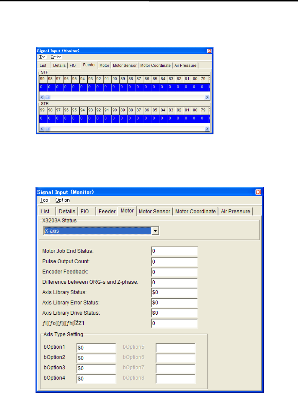
■ Feeder tab
“1” indicates that the feeder has been set.
“0” indicates that the feeder has not been set yet.
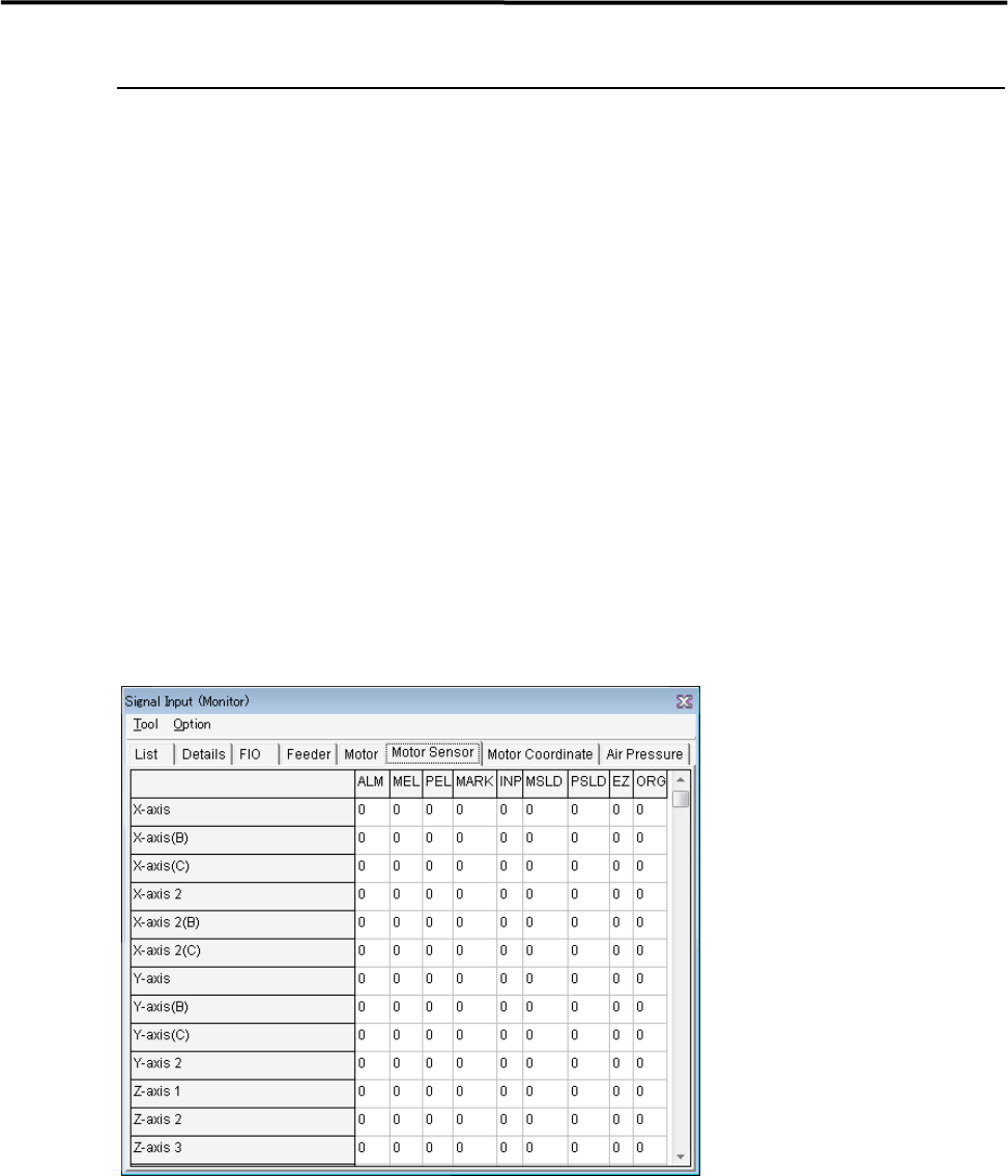
■ Motor tab
It can monitor the status of motors.