MIL- STD-883F 2004 TEST METHOD STANDARD MICROCIRCUITS.pdf - 第15页
MIL-STD-883F 9 4.1.2 Revi sions . Revis ions ar e numbered cons ecuti vely usi ng a period t o separat e the tes t method number and the revis ion number. For example, 4001.1 i s the f irs t revi sion of test method 4001…

MIL-STD-883F
8
3.1.13 Precision
. The degree to which an instrument, device, assemblage, test, measurement or process exhibits
repeatability. Expressed statistically or through various techniques of Statistical Process Control (SPC). Term is used
interchangeably with "repeatability".
3.1.14 Resolution
. The smallest unit of readability or indication of known value in an instrument, device or assemblage
thereof.
3.1.15 Standard reference material (SRM)
. A device or artifact recognized and listed by the National Institute of
Standards and Technology (NIST) as having known stability and characterization. SRM's used in product testing provide
traceability for technical specifications. SRM's do not require calibration when used and stored in accordance with NIST
accompanying instructions. They are used as "certified materials".
3.1.16 Tolerance
. A documented range over which a specified value may vary.
3.1.17 Test accuracy ratio (TAR)
. A ratio of the tolerance of the device under test to the accuracy of the related
measuring or test instrument or to the accuracy of the correlation device/SRM.
3.1.18 Uncertainty
. An expression of the combined errors in a test measurement process. Stated as a range within
which the subject quantity is expected to lie. Comprised of many components including: estimates of statistical distribution
and results of measurement or engineering analysis. Uncertainty established with a suitable degree of confidence, may be
used in assuring or determining product conformance and technical specifications.
3.1.19 Susceptibility
. The point at which a device fails to meet the postirradiation end-point electrical parameter limits or
fails functionally during radiation exposure (e.g., neutron irradiation).
3.1.20 Class M
. Class M is defined as 1.2.1 compliant product or product built in compliance to Appendix A of MIL-PRF-
38535 documented on a Standard Microcircuit Drawing where configuration control is provided by the Government preparing
activity. Class M devices shall use the conditions specified in the test methods herein for class level B product.
3.1.21 Class level B and class level S
. 2 class levels are used in this document to define requirements for high reliability
military applications (Class level B) and space applications (Class level S). Class level B requirements contained in this
document are intended for use for Class Q, Class H, and Class M products, as well as Class B M38510 JAN slash sheet
product. Class level B requirements are also intended for use for product claimed as 883 compliant or 1.2.1 compliant for
high reliability military applications. Class level S requirements contained in this document are intended for use for Class V,
Class K, as well as M38510 Class S JAN slash sheet product. Class level S requirements are also intended for use for
product claimed as 883 compliant or 1.2.1 compliant for space level applications.
4. GENERAL REQUIREMENTS
4.1 Numbering system
. The test methods are designated by numbers assigned in accordance with the following system:
4.1.1 Classification of tests
. The tests are divided into four classes:
1001 to 1999 Environmental tests
2001 to 2999 Mechanical tests
3001 to 4999 Electrical tests
5001 to 5999 Test procedures

MIL-STD-883F
9
4.1.2 Revisions
. Revisions are numbered consecutively using a period to separate the test method number and the
revision number. For example, 4001.1 is the first revision of test method 4001.
4.1.3 Method of reference
. When applicable, test methods contained herein shall be referenced in the individual
specification by specifying this standard, the method number, and the details required in the summary paragraph of the
applicable method. To avoid the necessity for changing specifications which refer to this standard, the revision number
should not be used when referencing test methods. For example, use 4001, not 4001.1.
4.2 Test results
. The data resulting from application of any test method or procedure shall be reported in terms of the
actual test conditions and results. "Equivalent" results (e.g., equivalent 25°C device hours or failure rate derived from 125°C
test conditions) may be reported in addition to the actual results but shall not be acceptable as an alternative to actual
results. Results of any test method or procedure shall be accompanied by information on the total quantity of devices in
each lot being tested on a 100 percent or sampling basis, the associated quantity of devices in the sample for tests on a
sampling basis, and the number of failures or devices rejected by test method and observed mode of failure. In cases
where more than a single device type (part number) is involved in the makeup of a lot for inspection or delivery, the data
shall be reported as above but with a further breakdown by part number.
4.3 Test sample disposition
. Test sample disposition shall be in accordance with A.4.3.2.1 of Appendix A of MIL-PRF-
38535.
4.4 Orientation
.
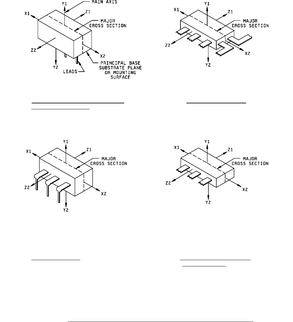
4.4.1 Identification of orientation and direction of forces applied
. For those test methods which involve observation or the
application of external forces which must be related to the orientation of the device, such orientation and direction of forces
applied shall be identified in accordance with figures 1 and 2.
4.4.2 Orientation for other case configurations
. For case configurations other than those shown in figures 1 and 2, the
orientation of the device shall be as specified in the applicable acquisition document.
4.4.3 Orientation for packages with different size lateral dimensions
. In flat packages where radial leads emanate from
three or more sides, the X-direction shall be assigned to the larger and the Z-direction to the smaller of the two lateral
dimensions.
*
MIL-STD-883F
10
FIGURE 1a. Orientation of microelectronic device to
FIGURE 1b. Radial lead flat packages.
direction of applied force
.
FIGURE 1c. Dual-in-line package
. FIGURE 1d. Flat package with radial leads
from one side only
.
FIGURE 1. Orientation noncylindrical microelectronic devices to direction of applied forces
.