MIL- STD-883F 2004 TEST METHOD STANDARD MICROCIRCUITS.pdf - 第323页
MIL-STD-883F METHOD 2018.4 18 June 2004 11 A NOTES: 1. Cr oss- sec tional pl anes are denot ed by dashed l ines. 2. Al l pass ivati on steps nonperpendic ular t o curr ent fl ow must be pr ojected ont o cros s- sect iona…

MIL-STD-883F
METHOD 2018.4
18 June 2004
10
3.11 Required data for nondestructive SEM validation
. Data demonstrating that the method is nondestructive as defined
in A.4.3.2.2 of Appendix A of MIL-PRF-38535 shall be submitted to the qualifying activity following the procedure detailed in
3.11.1 through 3.11.3.
3.11.1 Sample conditioning
. Expose a sufficient number of devices to the following conditions to yield a quantity of life
test samples that meet a quantity (accept number) of 45(0) for each validation sample:
a. Sample A: Expose at the worst case SEM operating conditions (i.e., accelerating voltage, absorbed specimen
current and tilt) and normal SEM metallization inspection procedure for a duration of 10 ± 1 minutes.
b. Sample B: Expose at the worst case SEM operating conditions and normal SEM metallization inspection
procedure for an increased duration of 30 ± 3 minutes.
c. Sample C: (Optional at the discretion of the manufacturer.) Control group without any SEM exposure.
3.11.2 Procedure
. Process test groups through all normal screening steps to complete post burn-in electricals, serialize
test samples, and complete 3.11.2a through 3.11.2d.
a. Data log variables on all 25°C dc parameters and record attributes data for all other group A electrical test
parameters, conditions and limits specified in the device specification or drawing (i.e., complete group A, not only
specified life test endpoints).
b. Place test samples, including the control group if applicable, on life test in accordance with method 1005 at 125°C
minimum for 1630 hours or equivalent (130°C for 1,135 hours, 135°C for 800 hours, 140°C for 565 hours, 145°C for
405 hours, 150°C for 295 hours, 155°C for 215 hours, 160°C for 155 hours, 165°C for 115 hours, 170°C for 85
hours, 175°C for 65 hours) with cooldown under bias using test condition C.
c. Repeat 3.11.2a for post life test endpoints.
d. Provide qualifying activity with one set of test results for each sample in terms of variables and attributes data on
pre and post life test endpoints plus analysis of mean and standard deviation of variables data and indication of any
devices which failed any group A test parameters.
3.11.3 Criteria for validating SEM as nondestructive
. If sample A passes single duration and sample B passes triple
duration SEM exposure and life test without failing any device specification or drawing parameters, conditions and limits (or
delta parameter requirements when they are specified), the SEM procedure shall be validated as nondestructive for the
process flow represented by the sample devices and for other devices from the same process flow. With the approval of the
qualifying activity, this SEM nondestructive qualification may be performed on appropriate process monitor structures or
standard evaluation circuits (SEC's) which represent the process flow.
4. SUMMARY
. The following details may be specified in the applicable acquisition document:
4.1 Detail 1
. Single wafer acceptance basis when required by the acquiring activity.
4.2 Detail 2
. Requirements for photographic documentation (number and kind) if other than as specified in 3.8.
*
MIL-STD-883F
METHOD 2018.4
18 June 2004
11
A
NOTES:
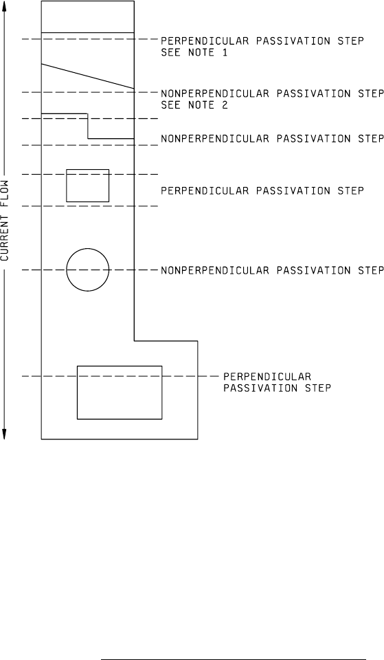
1. Cross-sectional planes are denoted by dashed lines.
2. All passivation steps nonperpendicular to current flow must be projected onto cross-sectional planes
perpendicular to current flow for purpose of cross-sectional area calculations.
3. The purpose of this cross-sectional plane illustration is two-fold:
To provide a consistent and convenient means to facilitate the calculation of the
appropriate cross-sectional area.
To insure that the cross-sectional area of the metallization in a major current
carrying direction is reduced to no more than 50 percent (30 percent when appropriate)
for the topographical variation under consideration.
FIGURE 2018-1. Cross-sectional planes at various passivation steps
.
MIL-STD-883F
METHOD 2018.4
18 June 2004
12
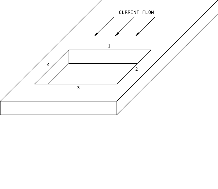
NOTES:
1. 1, 2, 3, and 4 are directional edges.
2. 1 is a major current carrying edge.
FIGURE 2018-2. Directional edge
.