MIL- STD-883F 2004 TEST METHOD STANDARD MICROCIRCUITS.pdf - 第353页
MIL-STD-883F METHOD 2019.7 07 March 2003 3 FIGURE 2019-1. Compliant i nterf ace on cont act t ool dis tribut es load to t he irr egular edge of t he die . FIGURE 2019-2. Rotat e the die c ontact tool or the devic e for p…

MIL-STD-883F
METHOD 2019.7
07 March 2003
2
3.2 Failure criteria. A device which fails any of the following criteria shall constitute a failure.
Note: (See examples for determining DIE AREA following figure 2019-4.)
a. Fails die strength requirements (1.0X) of figure 2019-4.
b. Separation with less than 1.25 times the minimum strength (1.0X) specified in figure 2019-4 and evidence of less
than 50 percent adhesion of the die attach medium.
c. Separation with less than 2.0 times the minimum strength (1.0X) specified in figure 2019-4 and evidence of less
than 10 percent of adhesion of the die attach medium.
NOTE:
Residual silicon attached in discrete areas of the die attach medium shall be considered as evidence of
adhesion. For metal glass die attach, die attach material on the die and on the package base shall be considered as
evidence of acceptable adhesion.
3.2.1 Separation categories
. When specified, the force required to achieve separation and the category of the separation
shall be recorded.
a. Shearing of die with residual silicon remaining.
b. Separation of die from die attach medium.
c. Separation of die and die attach medium from package.
4. SUMMARY
. The following details shall be specified in the applicable acquisition document.
a. Minimum die attach strength if other than shown on figure 2019-4.
b. Number of devices to be tested and the acceptance criteria.
c. Requirement for data recording, when applicable (see 3.2.1).
MIL-STD-883F
METHOD 2019.7
07 March 2003
3
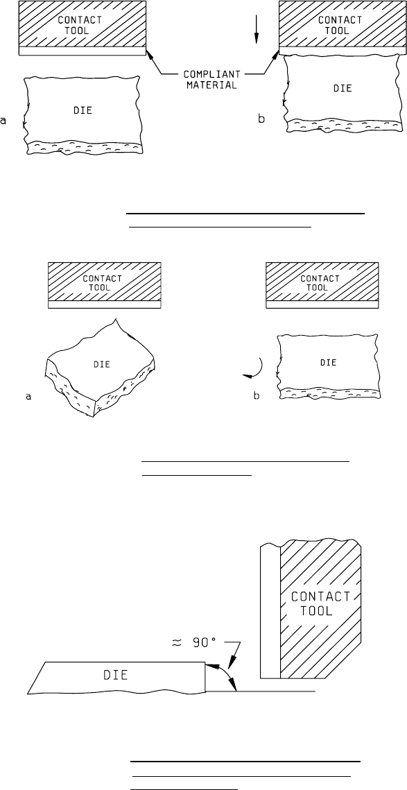
FIGURE 2019-1. Compliant interface on contact tool distributes
load to the irregular edge of the die
.
FIGURE 2019-2. Rotate the die contact tool or the device
for parallel alignment
.
FIGURE 2019-3. The contact tool shall load against that edge
of the die which forms an angle ≈ 90° with
the header/substrate
.
MIL-STD-883F
METHOD 2019.7
07 March 2003
4
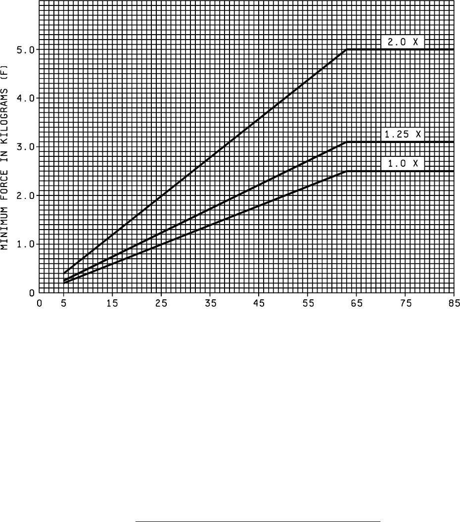
NOTES:
1. All die area larger than 64 x 10
-4
(IN)
2
shall withstand a minimum force of 2.5 kg or a multiple
thereof (see 3.2).
2. All die area larger than or equal to 5 x 10
-4
(IN)
2
but small than or equal to 64 x 10
-4
(IN)
2
shall withstand a
minimum force as determined from the chart of Figure 2019.4
3. All die area smaller than 5 x 10
-4
(IN)
2
shall withstand a minimum force (1.0X) of 0.04 kg/10
-4
(IN)
2
or a minimum force (2X) of 0.08 kg/10
-4
(IN)
2.
FIGURE 2019-4. Die shear strength criteria (minimum force versus die attach area)
.
DIE AREA (10
-
4
IN
2
)