MIL- STD-883F 2004 TEST METHOD STANDARD MICROCIRCUITS.pdf - 第309页
MIL-STD-883F METHOD 2017.8 18 June 2004 19 FIGURE 2017-9 Cent er cont act or ientati ons to s ubst rate. FIGURE 2017-10. Center Cont act over lap to s ubstr ate .
MIL-STD-883F
METHOD 2017.8
18 June 2004
18
Class H Class K
3.1.7 Screw tabs and through hole mounting, magnification 3X to 10X
. No device shall be acceptable that exhibits:
a. Misaligned tabs.
b. Missing or broken tabs.
c. Cracks emanating from mounting holes.
d. Loose substrates.
e. Missing or loose screws.
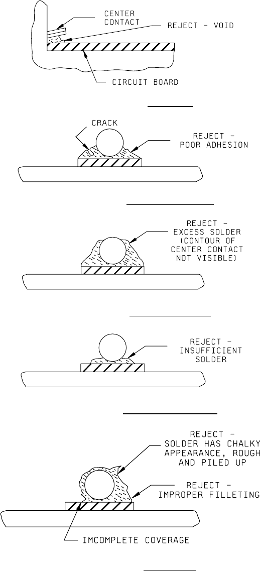
3.1.8 Connector and feedthrough center contact soldering, magnification 10X to 30X
. No device shall be acceptable that
exhibits:
a. Less than 50 percent of center contact overlaps onto metallized pattern (see Figure 2017-9).
b. Center contact to substrate protrudes over onto circuit less than 1 diameter of a round pin or the width of a flat pin
(see Figure 2017-10).
c. Voids in solder (see Figure 2017-11a).
d. Cracked solder joint (see Figure 2017-11b).
e. Poor adhesion of solder to center contact or substrate (see Figure 2017-11b).
f. Insufficient or excess solder (see Figures 2017-11c through 2017-11e).
g. Less than full coverage of solder along the length of the center contact and the metallization.

MIL-STD-883F
METHOD 2017.8
18 June 2004
19
FIGURE 2017-9 Center contact orientations to substrate.
FIGURE 2017-10. Center Contact overlap to substrate
.
MIL-STD-883F
METHOD 2017.8
18 June 2004
20
FIGURE 2017-11a. Void criteria
.
FIGURE 2017-11b. Crack/adhesion criteria
.
FIGURE 2017-11c. Excess solder criteria
.
FIGURE 2017-11d. Insufficient solder criteria
.
FIGURE 2017-11e. Solder criteria
.